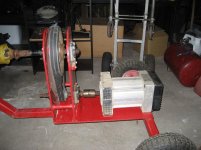
Single phase synchronous brushless alternator
Type MS100 SE
S1 (KVA) N070935627 60 HZ
3600 rpm
5.0 V A
240 20.8 IP21
120 41.6 PF=1
I don't have alot of money invested at this point.....what do I have?? What can it do?? What are its limitations?? Also came with a 30amp lockable plug.
What you have there is a 2pole (3600RPM), 120/240Vac split phase, 5KW alternator head. It will require about 8HP at the input. You must operate the alternator head at 3600RPM to get the correct voltages (120/240Vac) and the correct frequency 60Hz).
If you run the alternator head too slow, the output voltage will sag and the output frequency will be too low -- this condition is REALLY bad for motors and devices with transformers. You can burn them up this way, really quick.
If you run the alternator head too fast, the output voltage will be high and the output frequency will be too high. These conditions are bad as well for some types of gear. You should aim for an input speed of 3600RPM +/- 200RPM, which is about 5%. This span of variance will run the majority of typical electrical equipment without problem. In general you are usually better off a little high on input RPM versus a little low.
By the way, the IP21 designation means that the enclosure is drip-proof but you should not store it outdoors nor should you operate it in the rain.
Since your pulley ratios are ~4:1, your 540RPM PTO mode will not reach the necessary 3600RPM at maximum engine RPM. Your 1000RPM PTO mode will reach 3600RPM but at an engine throttle setting less than maximum RPM.
In general, the PTO setup on any tractor is geared such that 540RPM (or optionally selectable 1000RPM) is delivered at the engine's torque peak. In your situation, you will end up running your tractor engine below the torque peak to get the correct PTO RPM for the 3600RPM input to the alternator (approximately 900 PTO RPM in the 1000RPM mode).
In this case I don't think it's a problem at all, as you only need about 8HP to turn the alternator at full load. Your 18HP Yanmar should be able to swing that at the PTO, even with the reduced RPM. The individual who designed the pulley arrangement may have had a similar size tractor (or even larger) and geared the pulleys to take advantaged of the reduced noise/fuel consumption of the lower RPM. In other words, you don't need 30HP at the PTO -- with the engine screaming -- to make 5KW.
In order to set the output voltage/frequency you will need a DMM (digital multi-meter) or Kill-A-Watt meter plugged in BEFORE you attach ANY loads. Start the tractor, come up a bit from idle, engage the PTO in 1000RPM mode, and read the DMM display. Continue advancing the throttle until you have approximately 120/240Vac (depending on where you attached the leads), and approximately 60Hz. Go a bit on the high side. The initial load on the alternator will droop the voltage and frequency a bit as the voltage regulation circuitry goes to work. Once you have the correct output, then you can attach your loads.
Both 120Vac and 240Vac are available on the 30A receptacle. Unless you have a 240Vac load, like a large air compressor or deep well pump, you may not need the 240Vac at all. In that case you can build a cable and external junction box to utilize both legs of the split phase 240Vac on the 30A receptacle.
L1 -> N = 120Vac
L2 -> N = 120Vac
L1 -> L2 = 240Vac
ps:
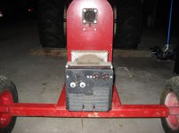
Always remember to keep the tractor PTO shaft in line as much as possible with the alternator input shaft. Any offset will result in "lumpy" AC as the rotational velocity of an offset shaft drive using universal joints is not constant.
More importantly, also remember that the "open" PTO shaft and pulley arrangement that you show in your pictures will tear your arm off (or worse) in a flash. Pay attention at all times, and do not let children or pets near the apparatus
Wrooster


")