JohnInCA
Bronze Member
For those of you considering a backhoe, here's something of interest. I have purchased a Bradco 408 backhoe and subframe mounting kit for a NH TC29D. I'm going to be posting pictures of the installation process as it progresses. First, a few comments about the subframe kit. It is designed so that no part of the 3pt hitch has to be removed when the backhoe is mounted. To install, the FEL must be removed (because the rear FEL mounts will be unbolted), and the rear tires must be removed. The subframe requires that four of it's pieces be welded together (two just "tacked"), and two of it's pieces must be tack welded to the tractor (I'll show all of this required welding in detail later). Now, let's get started with the pictures...
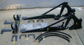
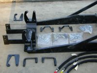
Here's a picture of the pieces of the subframe kit.
Part #1 - This is the portion that is bolted to the backhoe. It attaches to two hooks on part #2 (the top hook can't be seen, as I have the two parts hooked together at the top). This is the only part that comes off with the backhoe when it is removed.
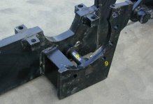
Part #2 - This is the main part of the subframe. The lower area (that has the "2" on it) is 1" thick steel plate. It bolts to the axle housing at the rear, and to part #5 at the front.
Parts #3 - These are straps that go over the top of the axle, and bolt to part #2, which is underneath the axle
Parts #4 - These are two large pins with handles which lock parts #1 and #2 together when the backhoe mounted on the tractor.
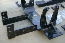
Part #5 - This piece bolts to the same holes as the rear mounts for the FEL.
Parts #6 - These are two spacers that go between the rear FEL mounts and part #5. (I guess I'll find out later why they used spacers here, instead of just making part #5 the correct dimension between the uprights)
Parts #7 - These two pieces bolt to the part of the tractor frame underneath the engine. They must be welded to part #5 after installed and all bolts tightened. The next picture will show how part #5 and parts #7 must be welded to each other.
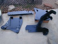
Here's a picture of the pieces of the subframe kit.
Part #1 - This is the portion that is bolted to the backhoe. It attaches to two hooks on part #2 (the top hook can't be seen, as I have the two parts hooked together at the top). This is the only part that comes off with the backhoe when it is removed.
Part #2 - This is the main part of the subframe. The lower area (that has the "2" on it) is 1" thick steel plate. It bolts to the axle housing at the rear, and to part #5 at the front.
Parts #3 - These are straps that go over the top of the axle, and bolt to part #2, which is underneath the axle
Parts #4 - These are two large pins with handles which lock parts #1 and #2 together when the backhoe mounted on the tractor.
Part #5 - This piece bolts to the same holes as the rear mounts for the FEL.
Parts #6 - These are two spacers that go between the rear FEL mounts and part #5. (I guess I'll find out later why they used spacers here, instead of just making part #5 the correct dimension between the uprights)
Parts #7 - These two pieces bolt to the part of the tractor frame underneath the engine. They must be welded to part #5 after installed and all bolts tightened. The next picture will show how part #5 and parts #7 must be welded to each other.