Rear Blade build

   / Rear Blade build #1  

MJPetersen

Veteran Member
Joined
Feb 23, 2007
Messages
1,255
Location
Warsaw, Poland
Tractor
YM 1510-D
This past fall I decided that my hobby needed to generate some income to pay for itself. With winter coming I thought that I should be able to do that by making a RB to plow snow for businesses and people here. That was my plan. But you know that while I read of all the snow in the States and the difficulties with the severe winter weather--we did not get any snow to speak of.:mad: So much for my income hopes! But this spring I decided to finish my project and to post my most modest efforts for your amusement,:rolleyes: or encouragement.

Those who remember my past threads know that implements for small tractors here are hard to find and generally expensive. So that is what prompted the build.

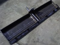
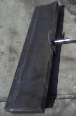
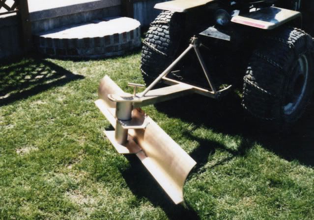
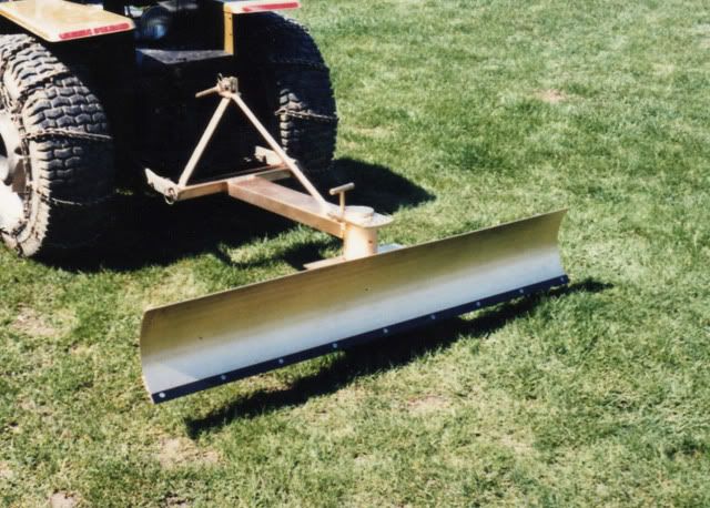
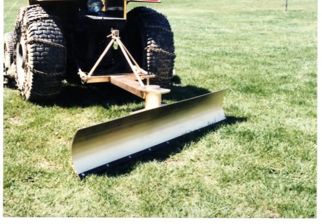
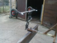
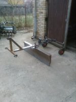
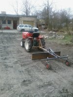
In order to make it truly economical I checked and found that I had most of what I would need in my scrap collection. I did need to get the main blade piece. I had it rolled to get the curve and I cut off the straight edges from the rolling in order to made the offset for the cutting edge.
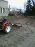
I also welded a straight back for the blade and triangular braces down on the cutting edge as my plan is to use this for more than a blade for snow.

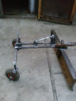
I want to use this with a metal cutting edge for dirt and a rubber edge for snow so I made a template which will double as the retainer for the rubber edge. I also want to have gauge wheels on it for super smooth finishes, so that had to be taken into account at the beginning.

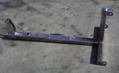
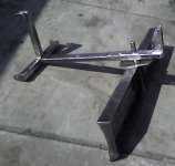
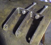
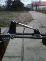
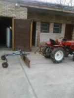
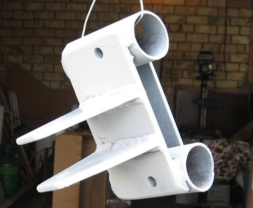
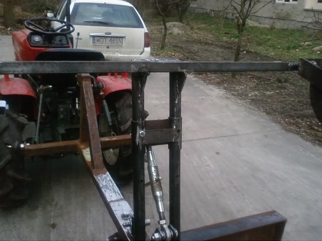
These first pics are of the 3pt frame and the blade. More pics will be forthcoming as I finish things.

Mike
 

Attachments

  • back of clade.jpg
    back of clade.jpg
    41.3 KB · Views: 4,324
  • Front of Blade.jpg
    Front of Blade.jpg
    21.6 KB · Views: 3,729
   / Rear Blade build
  • Thread Starter
#2  
The frame and 3 pt attach I was able to build from scrap that I had collected.:D I had to weld the tubing together to get the necessary lengths, but they worked and I think that they will be strong enough. I could not find material to get as tight a fit on the pivot pin as I would have liked, but I believe that it will be adequate for now.

The "F-18-hornet" double tail fin is for the gauge wheels that are in the works. I know that there is no extra bracing on the square tubing of the 3pt mount, but this tubing is fairly heavy wall and I believe that it will work without bracing. Maybe I will be embarrassed!:eek:

Mike
 

Attachments

  • main frame side.jpg
    main frame side.jpg
    18.4 KB · Views: 2,686
  • Frame and blade.jpg
    Frame and blade.jpg
    36.5 KB · Views: 3,080
   / Rear Blade build #3  
Nice looking blade so far. Some ideas I would consider to "beef up" the blade would be to weld gussets to the 3pt frame and the arm extending to the swivel point. Also, I don't know what the terrain is like where you are planning to clear, but if you catch the corner of the blade on a rock, There is a good chance that you will bend the post at the swivel. I have DESTROYED blades before just because I wasn't careful around that unsuspecting rock sticking up.
 
   / Rear Blade build #4  
Looks great so far, and I like that you wire brush all of your steel too!

I agree with Joe about adding the gussets to strengthen the whole assembly. The tubing may be heavy wall, and you may have good welds; but those are still hinge points that will be the first place the implement will want to fail.

Keep us posted with pictures.
 
   / Rear Blade build
  • Thread Starter
#5  
Thanks guys. I know that you are right about the braces--I actually had one for the verticle toplink mast, but did not like it so I took it out. I will add something there--at least a gusset.

Sorry for the not so nice pictures. I will try to do better with the next pics.

I have found that if you do not wire brush or use a flap disk on new steel it is hard to get paint to stick well.

Mike
 
   / Rear Blade build #6  
Hey Mike, another very nice looking project.
My hat is off to you using what you have and making it work. I'm sure you would have added braces and gussets as needed. You are pretty good about that.
You've always been very resourceful and I like your work!
 
   / Rear Blade build #7  
You are doing a great job on your back blade. Here are some pictures of my tractor when new and the back blade when new. I made it for my Dayton (MTD 990) tractor over 25 years ago. It has a Cat. 0 hitch. It will rotate right and left front and back 0,15,and 30 deg. I even added a removable scraper plate. It also has a grease fitting for the turning section. I use it all the time to clear snow in winter. It works great on loose soil and gravel.
DaytonTractor.jpg

DaytonwithScraper3.jpg

DaytonwithScraper4.jpg

DaytonwithScraper2.jpg
 
   / Rear Blade build
  • Thread Starter
#8  
Thanks guys for the encouragement. It helps to finish a project when you think that others might enjoy seeing your work and share in your triumph or failure at least vicariously. I know that is true for me as I see your masterpieces.

I finished the gauge wheel setup so that I could "test it out" on our parking area. I had smoothed it as best as I could with my BB but it was not where I wanted and I could not get it better so I decided to finish the gauge wheels for the RB.

Since they will not always be needed I made a way to raise them past vertical so that I could get as close to a building as possible. I used a sliding rear bracket that can be pinned in the down position or in the vertical position. Theoretically I could put more holes in the bars the make the frame and pin them in any position, but I could not think of a reason that it would be necessary.

I wanted to be able to spin the blade around so the wheels had to be a distance from the blade. The side benefit of that is the better "grader effect." The draw back is that the thing is so long. You really have to be aware or you will smack something when you turn sharply.

They also needed to be adjustable. I accomplished this in two ways; 1) I put a CAT 0 toplink that I was sent by mistake in the place where others could have placed a hyd cylinder, 2) I used washers for spacers for side to side fine tuning.

Mike
 

Attachments

  • Vertical.jpg
    Vertical.jpg
    110.4 KB · Views: 1,621
  • Wheels vertical.jpg
    Wheels vertical.jpg
    100.8 KB · Views: 1,630
  • assembled.jpg
    assembled.jpg
    101.3 KB · Views: 1,555
  • Wheel yokes.jpg
    Wheel yokes.jpg
    52.7 KB · Views: 1,323
  • hyd cylinder.jpg
    hyd cylinder.jpg
    111.3 KB · Views: 1,466
  • adjustment.jpg
    adjustment.jpg
    100.2 KB · Views: 1,537
   / Rear Blade build
  • Thread Starter
#9  
Well with it all together I just HAD to test it out on that rippled parking area.:rolleyes:

Overall I was very pleased with the result. I am working with fairly easy material (sand with some top soil) with NO rocks so the little slop in the pivot was not a problem. Some day I will take the time to make it tighter.:rolleyes:

I was pleased and gratified that the wheels help make it so much easier and faster to get things looking very smooth. :cool:

Now I have to clean things up, make some proper pins and retainers, and paint it.

Thanks,

Mike
 

Attachments

  • hooked up.jpg
    hooked up.jpg
    95.2 KB · Views: 1,519
  • Parking 1.jpg
    Parking 1.jpg
    132.1 KB · Views: 1,353
  • Parking 2.jpg
    Parking 2.jpg
    154.3 KB · Views: 1,483
   / Rear Blade build
  • Thread Starter
#10  
I am determined to figure out how you all post those tiny linked pics. I noted that you are using photobucket so I opened an account there and we will see how it works.

I was frustrated because it would be clearer if you could make comments and attach pictures to illustrate the explanation. So I am going to try to do just that.I finally figured out that a search on "thumbnails" got me the necessary info. Thanks to Jake (Grrrr) and Rob (3RRL).

What I think is unique about my build is not the blade itself--well I want to make a rake that will fit here too and therefore get double use of the frame and gauge wheels, but rather the gauge wheels and the control for them. There are times when getting them up and out of the way is beneficial--loading on a trailer, storage in your garage, working next to an obstacle, or simply knocking down a pile of material.

The method that I used to gain this versatility is a rear bracket for the adjusting link which is pinned in place on the structure bars. The wheels can be pinned up in two positions, but I prefer the "over center" position as it allows almost the same clearance as it has without wheels.


In this way you can change from the stored position back to the working position without loosing your position setting. Establishing the setting that will give you a smooth finish takes a bit of on/off the tractor.:(


I will follow up with the finished product hopefully this next week. I think that I have succeeded with the thumbnails--it took me an inordinate amount of time to figure it out :confused: but now that I have it I will be able to do better in the future. I know I should have just asked my teen age son, huh?!!

Thanks guys for bearing with me in my learning curve.

Mike
 
 
Top