Loader pin root grapple

   / Loader pin root grapple #1  

JustGary

Silver Member
Joined
Oct 24, 2005
Messages
182
Location
NW Florida, USA
Tractor
Kubota L2800 HST
All -

With all of this talk lately of grapples (and just getting 40 acres clear cut), I'm interested in one too. I'd like to just buy one, but I don't have (or want) a QA plate, and it seems that most of the available ones don't use pins.

After talking with Melissa at Markham Welding, I'm strongly considering getting them to cut and weld my design. I'm not opposed to doing it myself, but I'd rather save the time (and get much better welding).

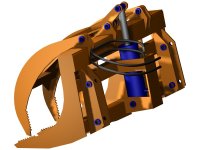
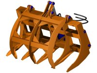
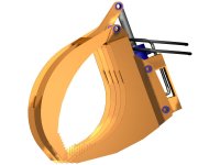
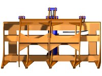
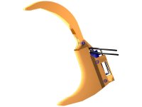
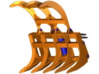
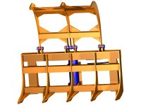
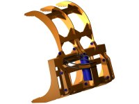
Anyway, one of the photos posted by a TBNer got me thinking about what I want, so I dusted off the ol' CAD program. Please feel free to comment on the design. Keep in mind that it is a 48" grapple for a 28 HP Kubota with the LA463 loader. Some key points:

- 48 3/4" wide
- 3/8" plate construction except for tubing
- Rake uses 3" square tube, 1/4" wall
- Grapple uses 2 1/2" square tube, 1/4" wall
- 1" pins throughout
- 8" stroke DA cylinder from Surplus Center
- Cylinder mounted behind rake for more protection, a distinct advantage over QA plate
- 100 degree jaw movement, opens to 46+" at tips
- Weight not calculated yet (I'm working on that next)

Questions for you to answer (I know I'm asking for it now...):

- Is it strong enough? I suspect yes, but you be the judge.
- Is it too strong? The loader is rated at about 1000 pounds lift, but curl (and ramming) forces are probably much greater.
- Should the grapple overlap the rake when closed (and loose opening distance)?
- What have I missed? Cupholders?

Regards,

- Just Gary
 

Attachments

  • Root_Grapple_1a.jpg
    Root_Grapple_1a.jpg
    70.2 KB · Views: 520
  • Root_Grapple_1b.jpg
    Root_Grapple_1b.jpg
    78.8 KB · Views: 386
  • Root_Grapple_1c.jpg
    Root_Grapple_1c.jpg
    51.6 KB · Views: 328
  • Root_Grapple_1d.jpg
    Root_Grapple_1d.jpg
    69.4 KB · Views: 272
  • Root_Grapple_1e.jpg
    Root_Grapple_1e.jpg
    31.5 KB · Views: 310
  • Root_Grapple_1f.jpg
    Root_Grapple_1f.jpg
    72 KB · Views: 309
  • Root_Grapple_1g.jpg
    Root_Grapple_1g.jpg
    66.8 KB · Views: 318
  • Root_Grapple_1h.jpg
    Root_Grapple_1h.jpg
    56.1 KB · Views: 311
   / Loader pin root grapple #3  
I really like the hydraulic cylinder behind the grapple, but do you think it will have enough clamping force with the cylinder attached so close to the pivot point of the grapple? If you think it will work, it looks great.
 
   / Loader pin root grapple
  • Thread Starter
#4  
mjncad: I used TurboCAD V15.1. I'm not in love with it (mainly because they break things as they add new features, then make the users prove that it doesn't work any more), but it works for what I need most of the time.

L4400: At the risk of doing math in public, I'll try to answer the clamping force question. I'm sure someone will correct me if I do it wrong (and please do).

Cylinder diameter = 3"
System pressure ~= 2300 PSI or so on a good day
Fulcrum to cylinder pin = 5.17"
Fulcrum to grapple tip = 30.15"

Piston area = 1.5" x 1.5" x pi = 7.07 sq. in.
Total force on piston pin = 7.07 sq. in. x 2300 PSI = 16,257.74 pounds
Force at tip of grapple = 16,257.74 pounds * 5.17" / 30.15" = 2787.81 pounds

Dang. That's more than I would have guessed, and I wouldn't want my parts near it when it closes. Thanks for making me do the math. I'm still working on the weight.

Regards,

- Just Gary
 
   / Loader pin root grapple #5  
That looks great! My only comment is to make sure the cage around the cylinder will clear the torque tube on your loader...I am pretty sure it would NOT on mine.
 
   / Loader pin root grapple #6  
Yeah, it does look great. Your CAD drawings are awesome.
I was going to make the exact same comment that Kenny made about clearing the torque tube.
Other than that, it's fantastic looking!
 
   / Loader pin root grapple #7  
Just Gary,

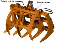
Your 3D drawing is superb! I'm having a hard enough time drawing 2D let alone something as eloquent as your grapple creation. Two concerns I would have are the tremendous forces present so close to the pivot point. See doctored drawing attached, the other is weight, without having all the surface areas to calculate weight, just looking at it my guess would be near 400 - 500 pounds? give or take. Does your CAD program have the "area" command ? I could be all wrong on my predicted stress failure points but it might be something worth looking at, maybe beef up the fulcrum arms past the pivot point?


Larry
 

Attachments

  • Just Gary Grapple.jpg
    Just Gary Grapple.jpg
    63.7 KB · Views: 603
   / Loader pin root grapple #8  
mjncad: I used TurboCAD V15.1. I'm not in love with it (mainly because they break things as they add new features, then make the users prove that it doesn't work any more), but it works for what I need most of the time.

Regards,

- Just Gary

All the software companies do that, just some more than others. I just loaded AutoCAD 2008 on my machine and it sucks compared to AutoCAD 2008. At least 2009 is not as bad as Release 11 & 13...so far.
 
   / Loader pin root grapple
  • Thread Starter
#9  
Just Gary,

Your 3D drawing is superb! I'm having a hard enough time drawing 2D let alone something as eloquent as your grapple creation. Two concerns I would have are the tremendous forces present so close to the pivot point. See doctored drawing attached, the other is weight, without having all the surface areas to calculate weight, just looking at it my guess would be near 400 - 500 pounds? give or take. Does your CAD program have the "area" command ? I could be all wrong on my predicted stress failure points but it might be something worth looking at, maybe beef up the fulcrum arms past the pivot point?


Larry

Larry -

Thanks for the compliment. 3D is not hard once you figure out that the program wants to work with 2D at a time. You just have to remember to tell it which 2D you want to work with at the time (the workplane). Figuring out how to make a particular part is a trick too, but the 3D extrude and 3D subtract are my friends most of the time. Plates and pipes are pretty easy, since you just enter the thickness you want.

On the pivot forces, I have nearly 20 inches of weldable joint when you look at both the butt into the square pipe plus the two gussets. At 1000 pounds per inch of weld, that's about 20,000 pounds. Granted, the force is high nearest the fulcrum, but at some point the 1" pin will shear and I won't have to worry about the welds any more.

The weight with 3/8" plate construction is around 350 pounds plus pins, cylinder, and the cylinder guard (I forgot it when calculating). The guard could easily be lighter material, though, so I'm not too concerned about it. I'm considering changing the larger gussets to 1/4", especially on the grapple. I would like the weight as low as possible, but I don't want to turn it into a pretzel just because I abuse it (which I will, I'm sure). The factory bucket is 1/4 material, yet seems incredibly strong. I have not been able to bend it, despite years of trying.

Regards,

- Just Gary
 
   / Loader pin root grapple #10  
Gary,
I was going to say what you said.
Granted, the force is high nearest the fulcrum, but at some point the 1" pin will shear and I won't have to worry about the welds any more.
The pivot point (pin an hole) is the focus of all the stress. I'm of the opinion (instead of the pin shearing), the 3/8" thick brackets would tear through the pivot hole or bend first. But i really don't think it's a problem. I'd build it today.
I'm with Larry, I'm a 2D hack too. I'd sure like to learn how to use the 3D and solid modeling features of the CAD system I have.
CAdKey 99
CadKey Workshop 21.5 ( I think)
Maybe you can't teach an old dog new tricks, or I'm just too lazy?:)
 
 
Top