An "axle-surrounding" type backhoe subframe

   / An "axle-surrounding" type backhoe subframe
  • Thread Starter
#11  
Re: An "axle-surrounding" type subfram
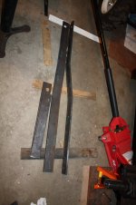
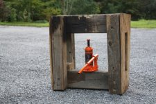
044.jpg017.JPGThanks Gunny & LD1.

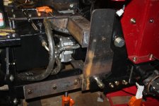
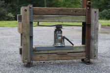
I wanted to share my experience with bending flat bar and plates. I had to bend the 1/2 x 3 inch flat bar that runs along side the loader subframe to create a 2 inch offset. (see first photo) As I don't have an acetylene torch, I needed to do the bend cold. I searched the web for help determining the force needed, but came up empty. As I don't have a shop press, I made a press using some old lumber from a defunct swing set and a 4 ton bottle jack. It creaked a lot, but held up. The press is not very pretty (second photo), but it worked. As the ends of press have openings, I can use any length of flat bar. Later in the project I had to bend 9 inch by 1/2 inch plate. The bends had to be much closer together than the bends in the 3 inch bar. When I get to that part of the project, I'll show the press I had to build and the forces involved.

The wood in the last photo was charred by my plasma cutter. Plasma cutting on a wood bench is probably not the smart thing I've ever done.
 
Last edited:
   / An "axle-surrounding" type backhoe subframe #12  
Re: An "axle-surrounding" type subfram

The vertical plate is 5/8 inch steel.View attachment 289401

That looks great, LEN!

That's one hefty piece of steel....did you cut it yourself with your plasma cutter? Nice.

Do you have pix of the backets on the hoe and how they attach to this part of the subframe?

On a side note, this photo is just the right size; most of your others are so big I can not easily
view them with my browser. Some browsers may automatically shrink them for viewing; mine does
not. I shrink all my posted photos to about 1000 pixels in the largest dimension (about 100KB file
size JPG files). You can do this with free editors, like what came with your computor, or I use a
cheap editor (Adobe Photoshop Elements) that does more stuff.
 
   / An "axle-surrounding" type backhoe subframe
  • Thread Starter
#13  
Re: An "axle-surrounding" type subfram

Thanks Dave for your your posts. As I said in my initial post the information you have provided has been invaluable.

I did cut the brakets with a plasma cutter (Longevity ForceCut 50i). The rest of the steel (mostly 1/2 inch) I cut with a 4 inch angle grinder. Because of my inexperience with the plasma cutter, the cuts were fairly crude and I was spending too much time cleaning them up with the grinder.

Going forward I will shrink the photos.

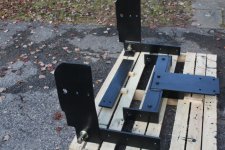
The following photo show the parts that permanently attach to the backhoe. It will connect at 4 points. Originally I was planning to weld 1 1/4 inch rods at the bottom of the backhoe brackets, but was concerned about the strength of the welds. Instead I bolted on Cat. 2 to Cat. 3 lower link pins. These pins are 1 7/16 inch diameter. The upper links were suppose to be pins, but after reading your posts I changed to 1 1/4 inch bolts. The picture below shows the finished parts laid out.
218 - Copy.JPG

The next series of pictures show how the connection is made.
205 - Copy.JPG241 - Copy.JPG
 
   / An "axle-surrounding" type backhoe subframe
  • Thread Starter
#14  
Re: An "axle-surrounding" type subfram

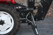
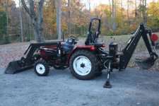
267 - Copy.JPGThe new subframe moves the backhoe 20 inches closer to the tractor as compared to when it was mounted to the 3 point hitch. If the PTO mounted pump wasn't in the way, I could have mounted it another 10 inches closer.

268 - Copy.JPG
 
   / An "axle-surrounding" type backhoe subframe #15  
Re: An "axle-surrounding" type subfram

Originally I was planning to weld 1 1/4 inch rods at the bottom of the backhoe
brackets, but was concerned about the strength of the welds. Instead I bolted on Cat. 2 to Cat. 3 lower
link pins. These pins are 1 7/16 inch diameter.

That's a good idea, esp since you are using cantilevered pins (supported on one side only). 3-pt
pins are very strong.
 
   / An "axle-surrounding" type backhoe subframe #16  
Re: An "axle-surrounding" type subfram

The new subframe moves the backhoe 20 inches closer to the tractor as
compared to when it was mounted to the 3 point hitch.

Nice. Have you noticed how much better the tractor drives now? And how much
more clearance you have at the rear (departure angle)?


If the PTO mounted pump wasn't in the way, I could have mounted it another 10 inches closer.

Sorry you could not get it closer. I know those Chinese tractors don't put out a lot
of flow/pressure from their own pumps.

Job well done.
 
   / An "axle-surrounding" type backhoe subframe
  • Thread Starter
#17  
Re: An "axle-surrounding" type subfram

Nice. Have you noticed how much better the tractor drives now? And how much
more clearance you have at the rear (departure angle)?

The most significant improvement I've noticed is how much better the backhoe handles. Now that the backhoe has a rigid attachment to the tractor, there is a lot more weight on the outriggers when they are deployed. This is especially helpful when pulling out stumps. When the backhoe was attached by the 3 point hitch, it was much easier to drag the tractor as only the weight of the backhoe was on the outriggers.
 
   / An "axle-surrounding" type backhoe subframe #18  
Re: An "axle-surrounding" type subfram

When the backhoe was attached by the 3 point hitch, it was much easier to drag the tractor as
only the weight of the backhoe was on the outriggers.

Oh, LEN, that's bad. Three point hitch setups for backhoe attachments come with a
bar to lock the 3PH into one position so it does not float. If it floats, as yours did, then
the whole hoe can suddenly rise and pinch you in a bad position. That can happen
in certain digging situations.

A correct 3PH installation of a hoe will result in the outriggers supporting the whole
rear of the tractor.
 
   / An "axle-surrounding" type backhoe subframe
  • Thread Starter
#19  
Re: An "axle-surrounding" type subfram

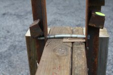
In an earlier post, I showed a home made shop press used for bending 3 inch x 1/2 flat bar. Later in the project I had to bend 9x1/2 inch plate to creat a 1 inch offset. These bends were much closer to each other, as compared to the bends in the 3 inch plate, requring a lot more force. I made a heftier press and used a 20 ton jack. Although I used much larger timbers and more lag bolts, it wasn't strong enough. I had to reinforce it with angle iron (left over from the tractor crates). The press worked, but some of the wood slit and the bolts bent (see 2nd photo). Each beam in the press was made up of smaller beams. They were tied together by only a few lag bolts. If I did a better job tying them together, its flexural strength would have increased significantly as they would have acted as a single unit. This was a temporary press that I've already taken apart. Once I have a larger shop, I've like to build a larger version using plywood and flitch plates.

021(sm).JPG023(sm).JPG

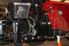
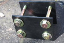
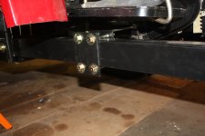
On the subframe, the 3x1/2 inch plate runs along the loader subframe, which is a rectangular tube. They're attached together at the bellhousing in front and again in the rear. I didn't want to bolt them together as I thought drilling holes through the loader subframe might weaken it. I wanted to use u-bolts, but couldn't find the right size. Instead I sandwiched them together using 2 plates and 4 bolts. This should help to increase its flexural strength.

256.JPG254(sm).JPG
 
   / An "axle-surrounding" type backhoe subframe
  • Thread Starter
#20  
Re: An "axle-surrounding" type subfram


Oh, LEN, that's bad. Three point hitch setups for backhoe attachments come with a
bar to lock the 3PH into one position so it does not float. If it floats, as yours did, then
the whole hoe can suddenly rise and pinch you in a bad position. That can happen
in certain digging situations.

A correct 3PH installation of a hoe will result in the outriggers supporting the whole
rear of the tractor.

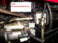
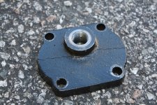
I bought the tractor, backhoe, and loader as a package. It was crated and came with no instructions or a bar to lock the 3PH. I only had a few pictures to help and no experience with tractors. In fact the pictures weren't always correct. I dead headed the first hydraulic pumped as the picture (from the factory!) was mislabeled. The notation at the top of the attached picture was mine in case someone sees this picture out of context of this thread. The second pictures shows the consequence.

100_1770.JPGIMG_7923.JPG
 
 
Top