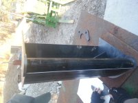
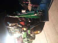
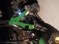
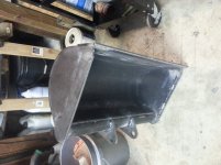
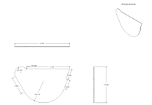
I've been wanting to build a ditch cleaning bucket for a while and I think a 24" is about all the 260 hoe can handle. Factory options are 8", 12", and 16". I have the 12" bucket which has a struck capacity of 0.66 cubic feet and weighs 49 lbs. The 24" bucket design should hold about 1.5 cubic feet (struck) and weigh around 90 lbs. The backhoe can only lift 285 pounds to a 36" height when the dipper and boom are fully extended. 1.5 cubic feet of dry soil is about 117 lbs, but wet soil could be up to 150 pounds, bringing total the total load on the bucket to a maximum of 240 pounds. This is really close to the lifting limits of the machine, assuming they measured the lifting capacity without a bucket.
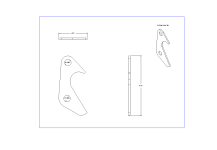
My intention for this project was to build the widest practical bucket without overloading the machine. I copied the dimensions of my existing bucket from the side. The design process was straightforward, but one thing I wanted to do was calculate the needed wall thickness for the torque tube that attaches the bucket sides to the dipper mounting tabs. The backhoe has a breakout force of 2,030 pounds at 19" according to the SAE rating method. This results in 38,570 inch pounds of torque acting on the bucket. I thought a reasonable thickness for the tube would be between 3/16" and 1/4" based on my "gut" feeling. Since the goal of this forum is to educate each other, I'll walk you fellas through the steps I took to firm up my numbers.
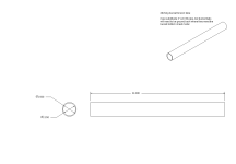
Let's choose 2.5" tube with a 0.25" wall. We will analyze the tube in both bending and twisting. The tube will be made from A500 structural steel which has a 36,000psi yield strength - the stress needed to bend it permanently. Structural steels have a shear modulus of about 11,457,981 psi. The shear modulus describes the material's response to being loaded in shear, like being cut with scissors. For reference, the shear modulus for paper is around 3,000 to 4,000 psi.
I know that seemed like a lot to understand in one pass, so basically, we're analyzing the tube in bending and twisting. To perform these analyses we need to know how strong the steel is. We have looked up two quantities, yield strength, and shear modulus, which contribute to our understanding of how the metal behaves when loaded.
Now that we know more about our materials, it's time to pick some simplified models of how the tube is loaded. First we will model the response of the tube to curling the bucket and stalling it out on a rock or something. Since the force is transmitted from the cylinder through the bucket ears to the tube to the sides of the bucket to the cutting edge, we can just simplify and say that worst case, our tube is fixed on one end (the bucket ear) and being twisted on the other end (from the bucket side). The force generated at the tip of the stock bucket is 2,030 pounds. Since our bucket is slightly shorter (no teeth), the force will be a little higher, but overall, the torque applied to the bucket will still be 38,570 inch pounds (force * distance). We will divide the torque in half since the tube is connected to both sides of the bucket. This makes our effective torque on the tube only 19,285 inch pounds. To calculate the maximum shear stress the tubing will experience, we use the following formula:
Max. Shear Stress for Tubing = torque * tubing radius / second moment of inertia
The second moment of inertia for tubing is 0.098174*(outer diameter^4 - inner diameter^4)
Substituting our numbers into the equations, we arrive at:
Second moment of inertia for tubing = 0.098174*(2.5^4 - 2^4) = 2.26415
Max. Shear Stress for Tubing = 19285*1.25 / 2.26415 = 10,647 psi
Since the yield strength for A500 steel is 36,000 psi and our maximum shear stress is 10,647 psi, the tubing should not permanently twist even if loaded at the maximum applied force. It would seem that the tubing could be further reduced in diameter, but let's consider a couple of other questiosn before making that decision: how much will the tubing twist and how will it behave under a bending load?
To calculate the deflection of the tubing as it is twisted, the formula is:
Angle of deflection = (length*torque) / (second moment of inertia*shear modulus)
The length is about 9" from one ear to the edge of the bucket and she shear modulus for structural steel is 11,457,981 psi. Therefore the angle of deflection is:
Angle of deflection = (9*19285) / (2.26415*11457981) = 0.00669 radians
To convert radians to degrees, multiply the radian result by 57.295:
0.00669 radians = 0.383 degrees.
This should be well within safe limits for bending without breaking any welds.
Finally, we analyze the tubing in bending. We choose a cantilever beam (completely fixed at one end, free to move at the other) for our model. The loading conditions would probably be half of the weight of the machine (around 1500 lbs) at 9 inches (nearest mounting tab to edge of bucket distance). The formula for maximum bending stress under these conditions is:
Max. Bending Stress = (load*length) / section modulus
The section modulus of a tube is: 0.78*(outer radius^4 - inner radius^4) / outer radius
Substituting in our numbers gives us a section modulus of: 0.78*(1.25^4 - 1^4) / 1.25 = 0.78*(2.44 - 1) / 1.25 = 0.8986
The maximum bending stress would be: (1500*9) / 0.8986 = 15,023 psi
Based on our analysis, the tubing wall can be lessened because both bending and torsional stresses are less than the yield strength of our material. The limiting factor will be loading in bending because it was larger than the torsional stress.
How would the numbers for 3/16" wall tubing look?
Max. Stress in Torsion (shear): 13,124 psi
Angle of Deflection in Torsion: 0.47 degrees
Max. Stress in Bending: 18,501 psi
What about 1/8" wall tubing?
Max. Stress in Torsion (shear): 18,278 psi
Angle of Deflection in Torsion: 0.66 degrees
Max. Stress in Bending: 25,768 psi
Considering the other factors such as this tubing is going to be welded to other 1/8" to 3/8" parts so there will be some point loads and I'm a crappy welder (there will be some undercuts), I wouldn't feel safe specifying anything less than 1/8" but I think I will order 3/16" to ensure that I don't burn through it!
Stay tuned folks! I'm ordering material tomorrow and I've already cut out the rest of the bucket.
Update: I just ordered the tube and since I'm cash strapped at the moment, I bought 2" SCH 80 A-500 pipe, which has a 2.375" OD and 0.218" wall. In a perfect world, I would have bought tubing instead of pipe, but I'll be able to make this stuff work okay. I'll just need more filler material around the smaller diameter when I weld the tabs.
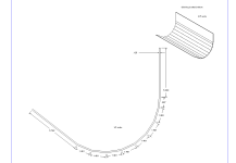
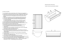
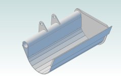
Cutaway drawing:
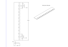
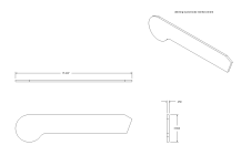
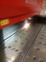
Using the laser cutter on the steel sheet I found in the scrap pile (likely mild steel):
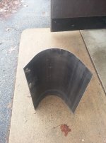
Rolled 1/8" bucket back:
My intention for this project was to build the widest practical bucket without overloading the machine. I copied the dimensions of my existing bucket from the side. The design process was straightforward, but one thing I wanted to do was calculate the needed wall thickness for the torque tube that attaches the bucket sides to the dipper mounting tabs. The backhoe has a breakout force of 2,030 pounds at 19" according to the SAE rating method. This results in 38,570 inch pounds of torque acting on the bucket. I thought a reasonable thickness for the tube would be between 3/16" and 1/4" based on my "gut" feeling. Since the goal of this forum is to educate each other, I'll walk you fellas through the steps I took to firm up my numbers.
Let's choose 2.5" tube with a 0.25" wall. We will analyze the tube in both bending and twisting. The tube will be made from A500 structural steel which has a 36,000psi yield strength - the stress needed to bend it permanently. Structural steels have a shear modulus of about 11,457,981 psi. The shear modulus describes the material's response to being loaded in shear, like being cut with scissors. For reference, the shear modulus for paper is around 3,000 to 4,000 psi.
I know that seemed like a lot to understand in one pass, so basically, we're analyzing the tube in bending and twisting. To perform these analyses we need to know how strong the steel is. We have looked up two quantities, yield strength, and shear modulus, which contribute to our understanding of how the metal behaves when loaded.
Now that we know more about our materials, it's time to pick some simplified models of how the tube is loaded. First we will model the response of the tube to curling the bucket and stalling it out on a rock or something. Since the force is transmitted from the cylinder through the bucket ears to the tube to the sides of the bucket to the cutting edge, we can just simplify and say that worst case, our tube is fixed on one end (the bucket ear) and being twisted on the other end (from the bucket side). The force generated at the tip of the stock bucket is 2,030 pounds. Since our bucket is slightly shorter (no teeth), the force will be a little higher, but overall, the torque applied to the bucket will still be 38,570 inch pounds (force * distance). We will divide the torque in half since the tube is connected to both sides of the bucket. This makes our effective torque on the tube only 19,285 inch pounds. To calculate the maximum shear stress the tubing will experience, we use the following formula:
Max. Shear Stress for Tubing = torque * tubing radius / second moment of inertia
The second moment of inertia for tubing is 0.098174*(outer diameter^4 - inner diameter^4)
Substituting our numbers into the equations, we arrive at:
Second moment of inertia for tubing = 0.098174*(2.5^4 - 2^4) = 2.26415
Max. Shear Stress for Tubing = 19285*1.25 / 2.26415 = 10,647 psi
Since the yield strength for A500 steel is 36,000 psi and our maximum shear stress is 10,647 psi, the tubing should not permanently twist even if loaded at the maximum applied force. It would seem that the tubing could be further reduced in diameter, but let's consider a couple of other questiosn before making that decision: how much will the tubing twist and how will it behave under a bending load?
To calculate the deflection of the tubing as it is twisted, the formula is:
Angle of deflection = (length*torque) / (second moment of inertia*shear modulus)
The length is about 9" from one ear to the edge of the bucket and she shear modulus for structural steel is 11,457,981 psi. Therefore the angle of deflection is:
Angle of deflection = (9*19285) / (2.26415*11457981) = 0.00669 radians
To convert radians to degrees, multiply the radian result by 57.295:
0.00669 radians = 0.383 degrees.
This should be well within safe limits for bending without breaking any welds.
Finally, we analyze the tubing in bending. We choose a cantilever beam (completely fixed at one end, free to move at the other) for our model. The loading conditions would probably be half of the weight of the machine (around 1500 lbs) at 9 inches (nearest mounting tab to edge of bucket distance). The formula for maximum bending stress under these conditions is:
Max. Bending Stress = (load*length) / section modulus
The section modulus of a tube is: 0.78*(outer radius^4 - inner radius^4) / outer radius
Substituting in our numbers gives us a section modulus of: 0.78*(1.25^4 - 1^4) / 1.25 = 0.78*(2.44 - 1) / 1.25 = 0.8986
The maximum bending stress would be: (1500*9) / 0.8986 = 15,023 psi
Based on our analysis, the tubing wall can be lessened because both bending and torsional stresses are less than the yield strength of our material. The limiting factor will be loading in bending because it was larger than the torsional stress.
How would the numbers for 3/16" wall tubing look?
Max. Stress in Torsion (shear): 13,124 psi
Angle of Deflection in Torsion: 0.47 degrees
Max. Stress in Bending: 18,501 psi
What about 1/8" wall tubing?
Max. Stress in Torsion (shear): 18,278 psi
Angle of Deflection in Torsion: 0.66 degrees
Max. Stress in Bending: 25,768 psi
Considering the other factors such as this tubing is going to be welded to other 1/8" to 3/8" parts so there will be some point loads and I'm a crappy welder (there will be some undercuts), I wouldn't feel safe specifying anything less than 1/8" but I think I will order 3/16" to ensure that I don't burn through it!
Stay tuned folks! I'm ordering material tomorrow and I've already cut out the rest of the bucket.
Update: I just ordered the tube and since I'm cash strapped at the moment, I bought 2" SCH 80 A-500 pipe, which has a 2.375" OD and 0.218" wall. In a perfect world, I would have bought tubing instead of pipe, but I'll be able to make this stuff work okay. I'll just need more filler material around the smaller diameter when I weld the tabs.
Cutaway drawing:

Using the laser cutter on the steel sheet I found in the scrap pile (likely mild steel):

Rolled 1/8" bucket back:

Last edited:
