Pull-Type Road Grader

   / Pull-Type Road Grader
  • Thread Starter
#11  
Ron,

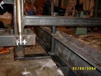
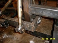
The two Cat I top links control the tilt of the blade. The one Cat II top link can be used to adjust the depth of cut, which also is controled by the three point lift. I'll try to get a better picture of it tomorrow to show you the pivot pins and how I connected the blade.
 
   / Pull-Type Road Grader #12  
Now all you have to do is hook up some hydraulics so you can adjust it from the tractor's seat. /forums/images/graemlins/wink.gif
 
   / Pull-Type Road Grader #13  
Nice job Bob.

I have a couple of questions of course.

1. What's all that white stuff on your lawn? And what does it do?

2. Tell us about your blade. Where it came from and how you mounted it.

3. I'm a little curious about about where you placed the wheels. If the grader is to just be used for grading a drive then I can see the wheels being so close. But if your plans are to also do some leveling with it then I wonder.

4. I'm also intrigued by not only how much weight you plan on using it but where you're going to put it.

Again congradulations on a fine job on a great project.
 
   / Pull-Type Road Grader #14  
Bob,
Great job.......
I can see in the pictures the pivot point for the rear top link. But the 2 side top links have me asking......Why 2? seems to me you'd have to shorten one while lengthening the other at the same time. Unless I just can't make out how it pivots at that point for tilt control.

But anyway........great job
 
   / Pull-Type Road Grader #15  
wroughtn_harv........
That white stuff is how we water our lawns in the winter season in areas North of Texas. It's magic.....go to bed at night wake up with that white stuff all over the yard.......Sun comes out........lawn watered /forums/images/graemlins/grin.gif
 
   / Pull-Type Road Grader #16  
Inspector, I had the same thought initally, but I'm sure each side adjuster raises/lowers that side of the blade for cutting depth.

I think one more pic from the front, showing the pivot, will help us both sleep better.

But it is a fine looking machine!

Ron
 
   / Pull-Type Road Grader
  • Thread Starter
#17  
Here is a picture of how I mounted the blade. The piece of steel on the bottom is 1"X3" with a 1-1/2" hole drilled in it. I used 1-1/2" round steel which pivots inside a schedule 80 pipe. I need to do some more welding on it and plan on adding some more bracing.
 

Attachments

  • 373694-blademount.JPG
    373694-blademount.JPG
    56.4 KB · Views: 1,487
   / Pull-Type Road Grader
  • Thread Starter
#18  
Here is a better picture of how I set it up to tilt. It may seem awkward, but it works pretty good. To tilt to the left rotate both top links inward at the same time. To tilt to the right rotate both top links outward at the same time. When you have the tilt you want, hold one and just give the other one a small twist to lock it. As long as the blade is raised I have been able to do it with very little effort. By using two it really locks the blade into a firm position.
 

Attachments

  • 373701-pivot.JPG
    373701-pivot.JPG
    52.1 KB · Views: 1,337
   / Pull-Type Road Grader #19  
Great Pics and great job Bob!

Looks like it will last for generations. Might need some gussets here and there, but looks pretty bulletproof from what I can tell.

Thanks for the extra pics!

Ron
 
   / Pull-Type Road Grader
  • Thread Starter
#20  
Harv asked about the blade. I had it made at a local machine shop. They took a piece of 1/4" X 84" steel and bent it every 1-1/2 inch to form the curve. It cost me $120, which included the price of the steel. About where I'm going to put the weight. If you look in some of my first pictures you will see a platform between and right in front of the wheels. This platform measures 21" X 37". I plan on casting a concrete block 21" X 37" X 13" high. This works out to be about 5.84 cubic feet. The density of concrete is about 150 lbs pcf. So this block should weigh about 875 lbs.
 
 
Top