You are using an out of date browser. It may not display this or other websites correctly.
You should upgrade or use an alternative browser.
You should upgrade or use an alternative browser.
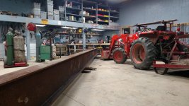
Building my bridge crane
- Thread starter LD1
- Start date
/ Building my bridge crane
#1
LD1
Epic Contributor
LD1
Epic Contributor
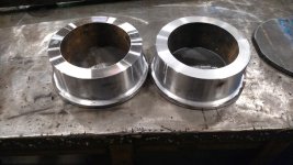
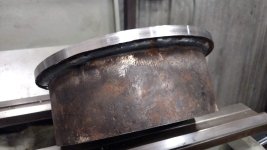
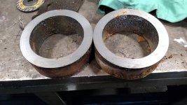
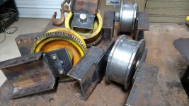
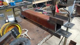
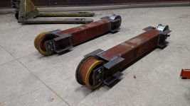
Next up is the end trucks. I already had 2 crane wheels 8" diameter and double flange. They are expensive to buy. I had a piece of pipe 8" od and 6" Id so I decided to make 2 more wheels.
Used a 3/8" plate for the flange, roughed in with the plasma, then cleaned up on the lathe.
Used a 3/8" plate for the flange, roughed in with the plasma, then cleaned up on the lathe.
Attachments
LD1
Epic Contributor
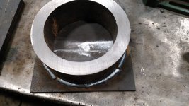
Once one flange was on, and everything turned true, I added the other flange. If I would have put both flanges on from the start, wouldnt have had a way to hold it in the lathe to true up.
Then bored out the flange plates to accept a piece of ~3.625" OD heavy wall pipe, that I counterbored for the bearings.
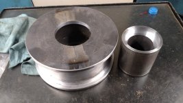
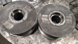
Then bored out the flange plates to accept a piece of ~3.625" OD heavy wall pipe, that I counterbored for the bearings.


LD1
Epic Contributor
LD1
Epic Contributor
Thats as far as I have gotten. I will post more pictures as I begin to "erect" the structure
franklin2
Gold Member
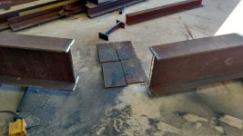
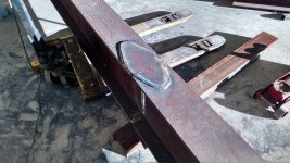
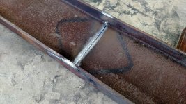
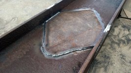
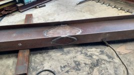
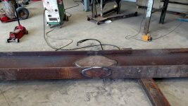
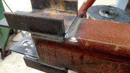
I have a question about your method of welding the patch on the side of the I-beam. So as to not clog up the thread you have going here on the build, I asked it in the welding forum here. http://www.tractorbynet.com/forums/welding/348348-proper-way-weld-patch.html#post4296445
Shield Arc
Super Member
I'm very interested in seeing how you mount the truck beams.
s219
Super Member
- Joined
- Dec 7, 2011
- Messages
- 8,608
- Location
- Virginia USA
- Tractor
- Kubota L3200, Deere X380, Kubota RTV-X
LD1, you do your homework and do good work, but please be sure to look into the effects of welding a patch in like that. I am not concerned with the patch or the welds (assuming they were done right, which is likely) but you are introducing a pretty significant non-uniformity/non-linearity into the beam with a joint, patch, and weld within the span. The upshot is that simple beam calculations/tables (and any factor of safety you thought you had based on them) go out the door. Factor of safety is only valid when the beam is consistent with the assumptions in the calculations. When it's not, the factor of safety is void.
Look at it this way -- the beam equations are based on the slopes and curvatures of the beam under flexural loading. There are assumptions about continuity. I think I touched on the calculus aspect of it in the other thread. When you increase the stiffness mid-span with a patch and welds, that is no longer a single continuous beam with continuous slopes and curvatures. You will end up with a stiffer flat spot at the patch and that makes it a different problem entirely.
Look at it this way -- the beam equations are based on the slopes and curvatures of the beam under flexural loading. There are assumptions about continuity. I think I touched on the calculus aspect of it in the other thread. When you increase the stiffness mid-span with a patch and welds, that is no longer a single continuous beam with continuous slopes and curvatures. You will end up with a stiffer flat spot at the patch and that makes it a different problem entirely.
Streetcar
Veteran Member
S219
If you look at any bridge that has been repaired , there are non uniform areas. Most bridge beams start out non uniform if you look at bracing and stiffeners installed.
As long as LD does a good job welding, which it appears he is, he is nor causing significant problems. Stiffer areas will pull some load from the weaker areas.
