3-point Hitch Design Tool

   / 3-point Hitch Design Tool #1  

B7510

Bronze Member
Joined
Feb 21, 2004
Messages
65
Location
Michigan - North of the 45th
Tractor
B7510
I just started into the realm of "make it yourself" and ran into a problem. I had a couple of 3-point impements that I wanted to build. I wanted to know how the dimensions between the 3-point connection pins on an implement affected the way the implement tilts when lowered and lifted.

I knew that I wanted my carry-all to stay at about the same angle when it was lifted. I also knew that I wanted my rock carrier to tilt back. The idea of having to get off the tractor and adjust the top link as I lifted the 1,000# rock didn't seem like the way to go.

I looked around and couldn't find anything that would give me any direction, and I kept getting diffeerent answers when I asked different folks. Well, I finally decided that when all else fails, you just have to set down for a while and figure it out.

It took me quite a while. I had to reach back 30 years and dust off my high school geometry a bit. But I think I finally got it.

Attached it a spread sheet file. It allows you to put in the basic dimensions for your tractor, lift range for your lower links, and a couple of dimensions for the implement. It then calculates how the angle of attack for the implement changes as the lower links are raised. I even got it to give you a little cartoon of the results.

You will need Microsoft Excel to run this. If you have another spread sheet let me know and I will see if I can do a "Save As" to get it into a workable format.
 
   / 3-point Hitch Design Tool #2  
You could have searched for the asae cat 1 specs.. and it would have given you height of the toplink, and distance between pins.. etc...

As for the toplink adjustment.. well.. that's justt he way it is.. and generally you adjust it before the 1000# rock is on there, as all you have to do is run the 3pt up to see the angle ont he implement. Aside from that.. many use a top-n-tilt setup which is essintially a hydraulic top and side link... adjustments on the fly...

good luck..

Soundguy
 
   / 3-point Hitch Design Tool #3  
Exact same dilhema I had when I built my 3PH for my MH. I wanted to get the perfect arc to maintain a level lift as you say. The ideal in any hitch system design I feel is to get the top link vertically in line with the lift arm link viewed from the side. My IH is off by about 6inches, so it's a design feature. The problem is the lift arm links are attached on the sides of the housing, and that defines an arc similar to a rocket's path. As it goes straight up, it eventually turns to one side.

I learned to live with the annoyance, but it gave me the worst headaches in plowing. I had to set the tractor 6inches higher on a flat surface, then drop the plow lower and level by 6inches which would be my draft. Then I'd head for the field with the plow tilted way backward in full raised. My top link was multicolored indicating the adjusting position of every implement. /forums/images/graemlins/grin.gif Finally sold it and now I use a 2 bottom MH#26 (1930?) on rubber with my IH, even though I can use a 3PH plow. Something wholesome about seeing an 'ole timer outdo the newbies in plowing.
 
   / 3-point Hitch Design Tool #4  
B7510,

I DL'd your spreadsheet, but I haven't looked at it yet. I was going to do something similar, but it looks like you might have saved me the trouble.

I'm not sure folks understand this...or maybe I didn't read your post right. My understanding is that this is for building/modifying your own impliments to take advantage of the tipping or non-tipping action according to how you want the impliment to work. There are two things that affect the way the impliment pitches when raised/lowered: the distance between the arm pins and the top link pin, and the length of the top link. The top link is variable, and it will alter the path from the perspective of where it is in it's predefined arc...but most of the time you're stuck with whatever arc you have because that's determined by the distance between the top and bottom pins of the implement.

I am assuming that using your tool you could figure out what that distance should be for either a level lift or a sharp tipping lift of an implement you want to build.

I just say all this because I find tremendous value in your tool (if it works /forums/images/graemlins/wink.gif ) for the building and/or modification of implements, and I wasn't quite sure whether I was getting it or not based on the replies I had seen so far.

Sam
 
   / 3-point Hitch Design Tool #5  
Hi B7510,

Thanks for the nice SS! It's definitely going in my collection!

I do the same thing as you, but use CAD. I draw a skeleton with correct pivot dimensions and geometry, then simply rotate the whole thing on the appropriate pivots. Works great, but it's not as elegant as your solver.
 
   / 3-point Hitch Design Tool
  • Thread Starter
#6  
Sl3uth,

It sounds like you got it.

I have checked it out by comparison to a carry-all and back blade that have different vertical seperation between the pins. The calcs seem to be correct. Nothing like seeing it actually work with metal to give you faith in the calculations.

I built the carry-all with a vertical pin seperation that matches the tractor (12.75" for a B7510). That keeps the platform at the same angle, regardless of lift height. My back blade has a significantly larger seperation, about 17". It tilts back a bit as it is raised.

I plan to build a 3-point rock carrier for hauling large landscaping rocks. I needed to figure out how to get the forks tilted slightly down when loading and then tilt a bit back towards the tractor when raised for traveling. Based on the calcs, I need almost 24" pin seperation and the forks need to be tilted down about 20 deg when the line between top and bottom pins is vertical. When raised it should tilt back about 20 deg towards the tractor.

I am sure I will still use tack welds to hold it together to check range of motion before I start burning up a lot of wire. This way, I at least have reasonable hope that I won't be cutting up expensive steel just to weld it back together and try again.
 
   / 3-point Hitch Design Tool #7  
Thanks for the spreadsheet. It makes the calculations really simple. /forums/images/graemlins/cool.gif Can't wait to get out and measure my tractor 3 PT.
 
   / 3-point Hitch Design Tool #8  
My 3pt bale carrier has a clamp for an upper link. The clamp (heavy duty!) can be clamped around a vertical square tube to any spacing. This is real handy, as it allows one to change the tilt. I can use it on cat 1 & cat2 tractors & make it work right since it is adjustable.

You might want to use 2 angle irons with several holes, or a clamp-on top link arangement, so that you are not stuck in just one set of angling on your rock lift. About as simple to make it adjustable now as to build it to one arc.

--->Paul
 
   / 3-point Hitch Design Tool #9  
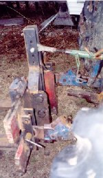
yea making the toplink mount adjustable is very helpfull, especialy if you dont have a hyd toplink, i made a set of forks a while back and at the time had no hyd toplink so i made 5 holes for the toplink, it worked nice to vary the tilt of them
 

Attachments

  • 431998-3ptforks sidesm.jpg
    431998-3ptforks sidesm.jpg
    48.1 KB · Views: 1,602
   / 3-point Hitch Design Tool #10  
Was just going to build a toolbar for the 3 pt where I could mount hiller bedmaking disks in the spring or pallet forks or ????? in the future. Thanks for working all this out!
 
 
Top