Homemade Articulated Mechanical Thumb

   / Homemade Articulated Mechanical Thumb #1  

3RRL

Super Member
Joined
Oct 20, 2005
Messages
6,825
Location
Foothills of the Giant Sequoia's, California
Tractor
55HP 4WD KAMA 554 and 4 x 4 Jinma 284
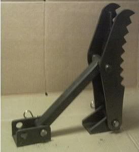
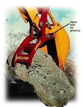
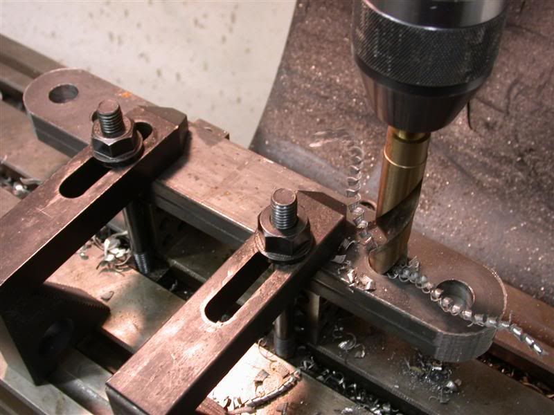
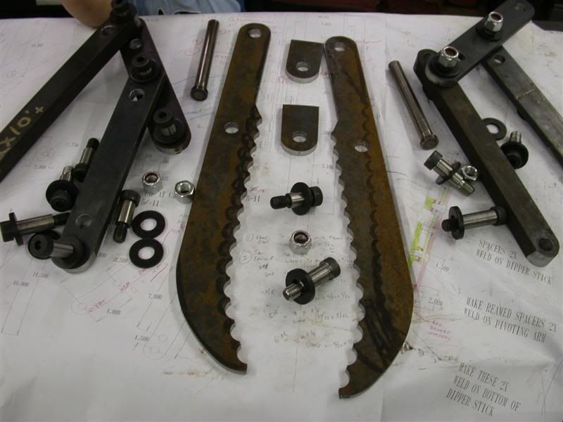
I've been wanting to make a "Thumb" for my backhoe for quite some time now. Among other things, I thought it would come in especially handy for placing rip rap rocks in my gutters just before the culverts. Many of the culverts are dug down beside the road and I could reach in there to place the rocks pretty easy with the backhoe. With that in mind, I started a small collection of different thumbs guys have made or bought for their backhoes.

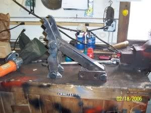
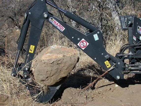
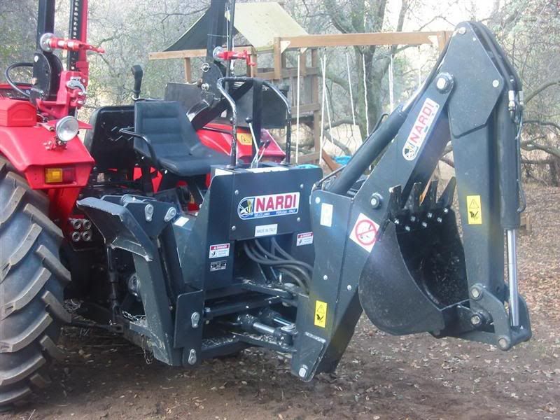
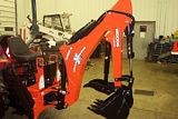
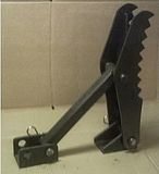
I got a lot of pictures but here are a few I "borrowed" from other threads. These are all fixed thumbs, and some can be adjusted to different positions.


   / Homemade Articulated Mechanical Thumb
  • Thread Starter
#2  
Here are a couple of shots of my Nardi Italian made backhoe. It is pretty beefy and is the 7-½' model. I've done quite a lot of digging with it already and some rock moving too.


Since I installed the bucket grapples for the fel, I don't need to pick up giant rocks with the backhoe, but I'm looking for something a little more nimble and I came across this thumb that moves back and forth without using a hydraulic cylinder.

 
   / Homemade Articulated Mechanical Thumb
  • Thread Starter
#3  
I thought that would be pretty cool to have on my backhoe too. So I made up some sketches of how I would have to make mine work that way. Fortunately, I some pin locations and some other dimensions written down so I could try to figure it out, but as it turns out, I'm going to need several more measurements that I didn't think of. Anyway, here's an idea I came up with and I think it will work once I get all the missing dimensions.

 
   / Homemade Articulated Mechanical Thumb
  • Thread Starter
#4  
Realizing that the pivot point locations will be critical to get this idea to work, I started to lay it out on my CAD system. At this point, I had to guesstimate some of the shape and width of the backhoe components and these will have to be confirmed. But in any case, the concept seemed like I can get it to work on my backhoe.


Using the concept, I rotated the linkage to different positions to see how they affect each other. I made several different attachment points and varied the connections on the articulating links to see what effect they would have. So I'm planning to have a couple of additional connection pivot holes in each link which results in the jaws closing slower or faster, opening farther or closer depending on the position of the bucket. I want to be able to pick stuff up when the dipper stick and boom are stretched out but also when they are folded, closer to the tractor. Having a couple of different pivot points will let me accomplish this.

Here is another CAD picture showing the bucket as it rotates in and how the jaw starts to meet it. Again, I can make the jaw meet it very soon or delay the jaw to allow more bucket curl.


I would like to use the cam method, but that's a lot easier to figure out when the bucket pivot and thumb pivot are on the same pin. Mine will not be and I have to work with what I got. In any case, the articulating linkage seems to be fine to move the jaws. It also allows several jaw positions.
 
   / Homemade Articulated Mechanical Thumb
  • Thread Starter
#5  
I'm leaving for the property tomorrow to do a bunch of work up there, but also to get the other measurements I need to verify ... or change the drawing concept. In the mean time, the jaws are not going to change nor the articulating linkage. Only the connections to the backhoe dipper stick may have to change and of course the width of the pivot hole brackets that will be welded to the backhoe. I've chosen the jaws to be 12" wide, so the thickness of the linkage bars and hardened washer will require a certain width when it's all connected to the backhoe dipper stick.

Anyway, I started machining the jaws by drilling out the shape.


I dialed off center to center plus .005" to leave a super thin "web" between the holes so the pices would not fall off on the last hole and catch my drill and bust it. Then I took a chisel and tapped the webs free. The remnant fell off and I had part of my shape.

 
   / Homemade Articulated Mechanical Thumb
  • Thread Starter
#6  
Then I stuck in a 1" corncob mill (roughing endmill) and started to cut the handle and radius on the piece.


After that, I started to cut the radius on the back side of the tips of the jaws. Notice also that I milled off all the sharp ends on the teeth and left a 3/16" flat on them.


After milling, I went over to the dics sander and blended the cuts in. This way I was able to smooth out the surface and generate somewhat of a real radius on the handle and the curve on the back of the jaws. My blueprint was the black marker line. :D
 
   / Homemade Articulated Mechanical Thumb
  • Thread Starter
#7  
After getting the jaws the way I wanted, I started on the linkage. There are 3 linkage bars on each side and I sawed and milled them to length, then drilled them for the all the pivot holes. I will be using ؾ" shoulder bolts for all the pivot pins. They have a 5/8-11 thread on the end and socket heads on the other.


So after all that, this is what I got so far.


Oh, I also started to turn up the pivot bases that will be welded to the backhoe, but have not finished them. I'll need to get the width of the dipper stick and the width of the actuating link on the backhoe so I can make the shoulder bolts bottom out without pinching the linkage. I'm leaving at 4:00 am tomorrow so I'll sign off for now. Let me know what you think so far...
 
   / Homemade Articulated Mechanical Thumb #8  
3RRL said:
After getting the jaws the way I wanted, I started on the linkage. There are 3 linkage bars on each side and I sawed and milled them to length, then drilled them for the all the pivot holes. I will be using ؾ" shoulder bolts for all the pivot pins. They have a 5/8-11 thread on the end and socket heads on the other.


So after all that, this is what I got so far.


Oh, I also started to turn up the pivot bases that will be welded to the backhoe, but have not finished them. I'll need to get the width of the dipper stick and the width of the actuating link on the backhoe so I can make the shoulder bolts bottom out without pinching the linkage. I'm leaving at 4:00 am tomorrow so I'll sign off for now. Let me know what you think so far...

I think I would like to see the pictures. Did they not get attached?
 
   / Homemade Articulated Mechanical Thumb #9  
I used to work for an outfit that designed and built bucket thumbs. Unless you use a common piviot point, whatever you are carrying will "roll" in the thumb/bucket. Use your CAD to roll the bucket and thumb. You'll see how the thumb will be closer and further away as you roll the bucket. Our boss tried to get us designers to make a thumb that was prebuilt that would be welded onto the stick (excavator arm), but it wouldn't work due to the rolling effect. That made grabbing then rolling out the bucket impossible to do without dropping what was carried.

What we had to do was bore/ream out the piviot bushing and use a larger diameter hardened pin that shared the duty of bucket and thumb.
 
   / Homemade Articulated Mechanical Thumb #10  
Rob,

Sounds like an interesting prject!!!

I've thought about the Amulet system a few times myself, but the standard thumbs are so much easier to make, and I wonder which one is really better.

I'll be following your progress and I'm especialy interested in your observations after you have used it awhile.

Thank you,
Eddie
 
 
Top