360* Rotating Back Blade Project

   / 360* Rotating Back Blade Project #1  

GuglioLS

Veteran Member
Joined
Feb 13, 2005
Messages
1,143
Location
Edgewood, NM USA
Tractor
Jinma 354, 1953 Ford NAA Golden Jubilee, Komatsu Bulldozer
I hope you find this an interesting story and project, it has many different paths along the way that lead to an incredible friendship and collaborative effort. If it were not for an interesting turn of events, the results of what you are about to see would not have been possible -

This will take you through concept to completion (sooner or later, probably later):

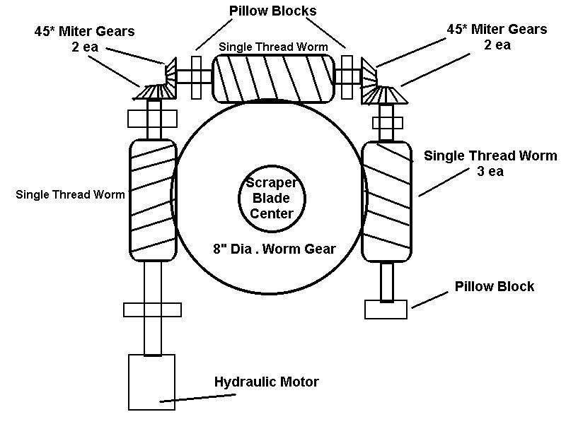
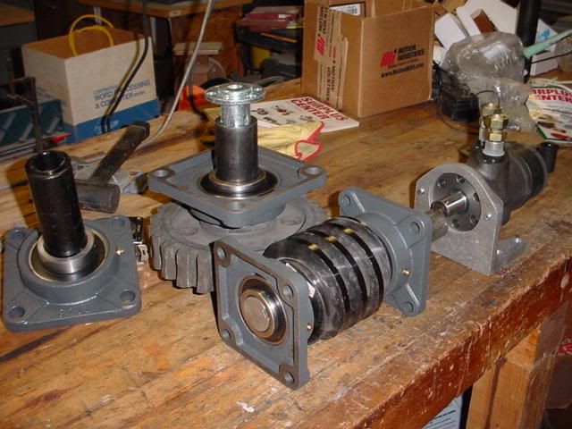
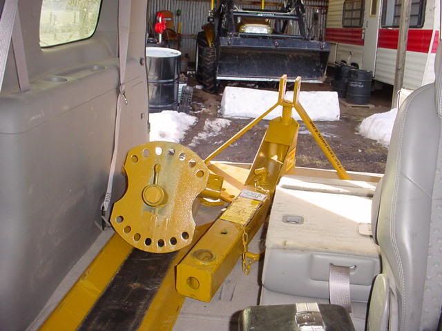
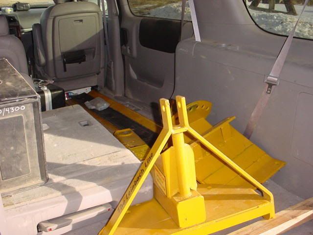
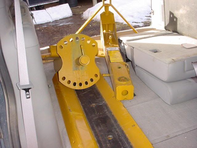
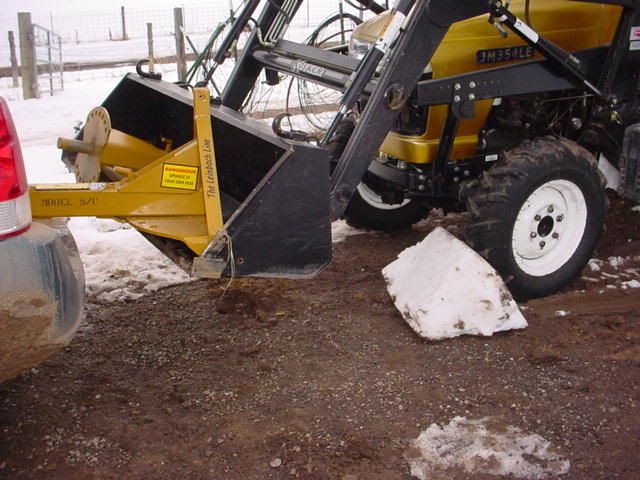
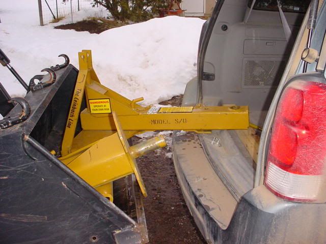
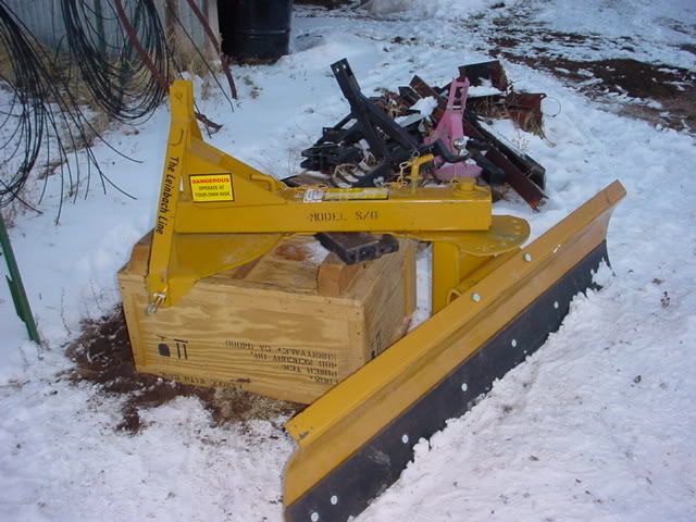
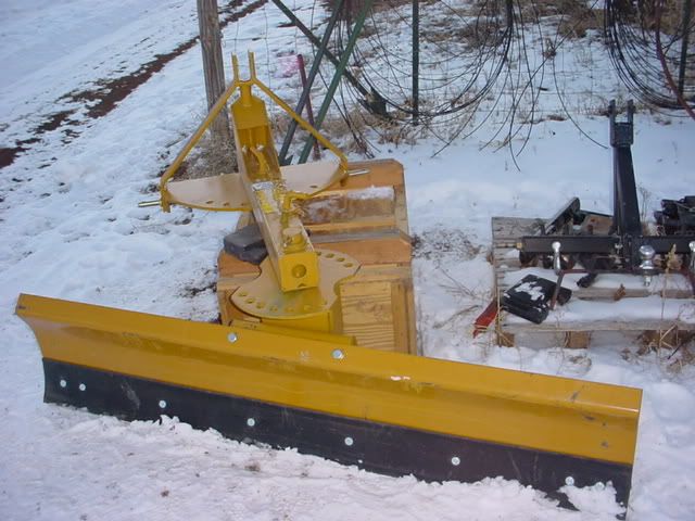
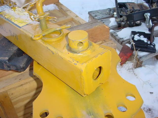
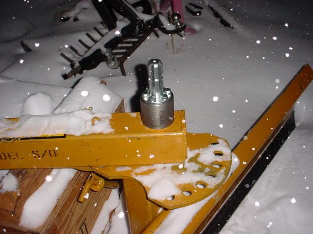
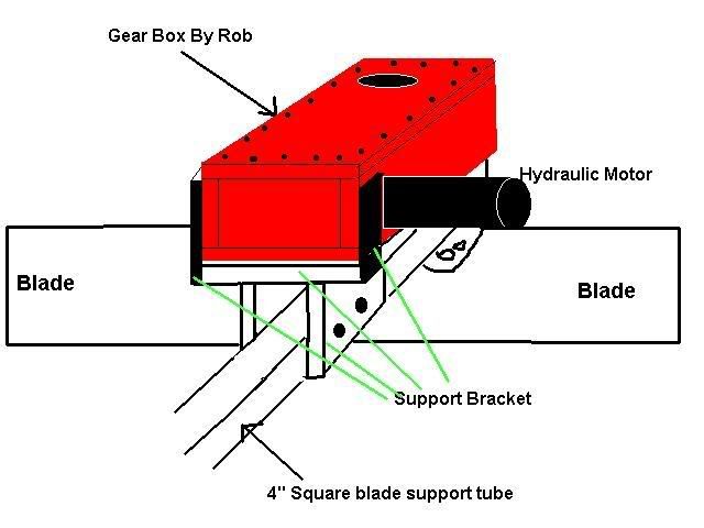
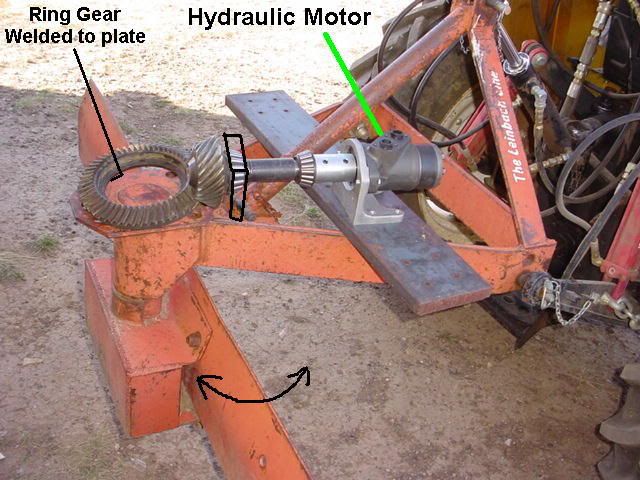
I got an idea a while back to make the rotational angle of my Back Blade automated. I was constantly getting off & on the tractor to adjust the blade angle for leveling dirt, plowing snow, cutting ditches, etc. I also reverse the blade and back drag the cutting edge for smoothing out high ridges. Anyway I've been thinking about this for quite a while. I've seen a few members that put hydraulic cylinders on them – and they are way cool. I am hoping this project will take their idea to the next level. With this setup I can rotate the blade 360* and everything in between. So I started kicking around some ideas starting with the following concept:


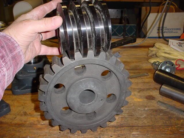
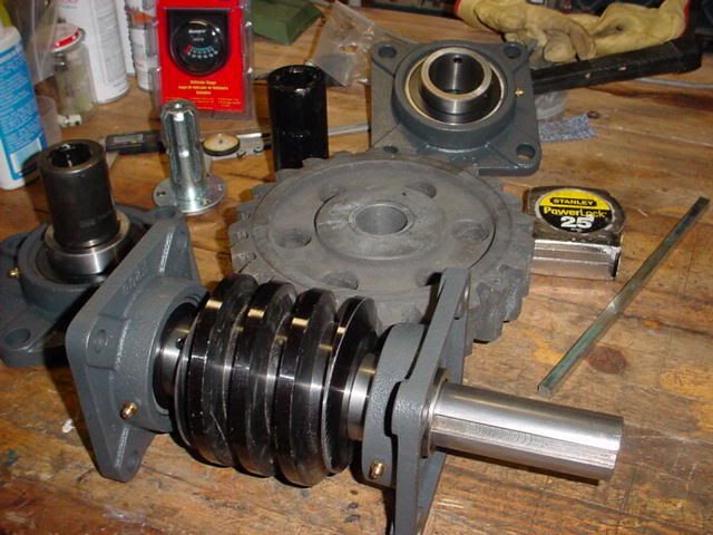
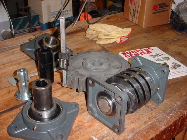
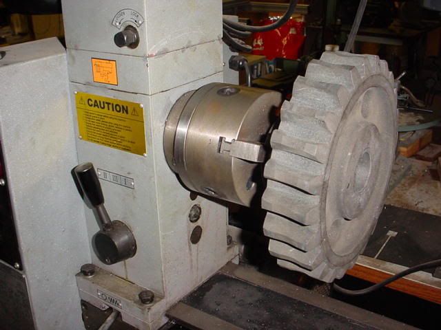
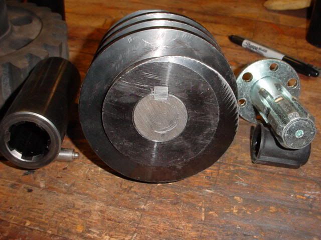
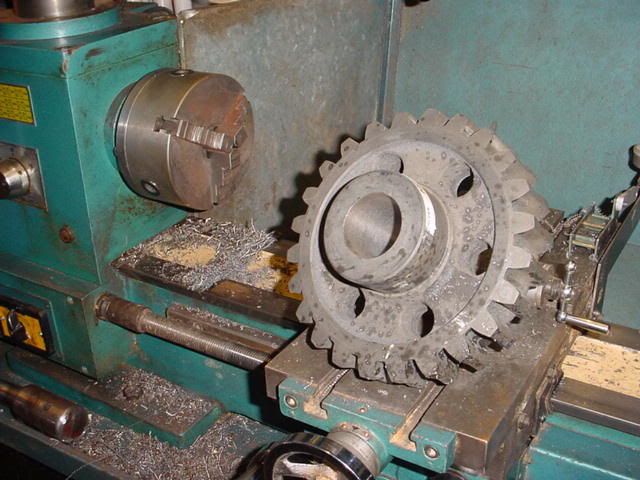
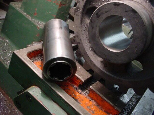
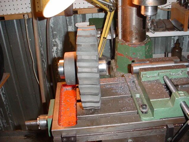
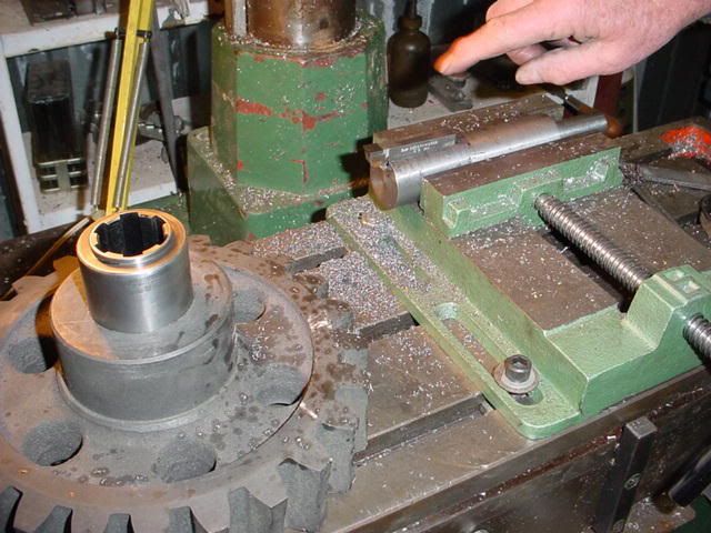
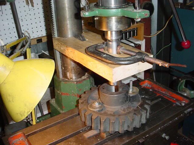
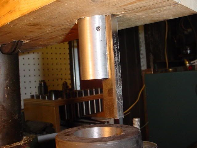
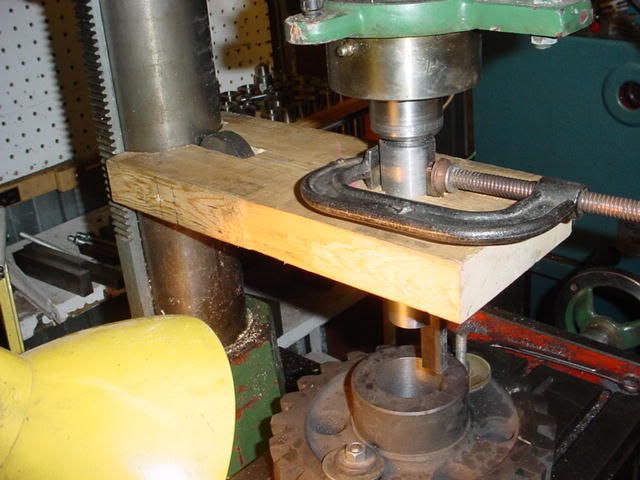
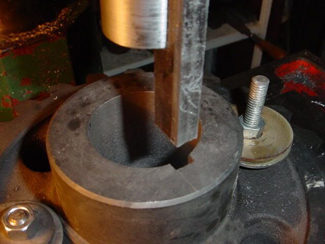
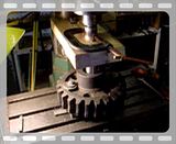
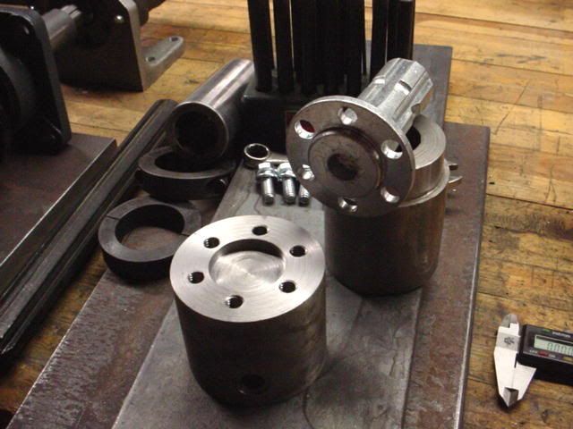
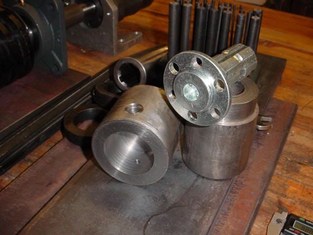
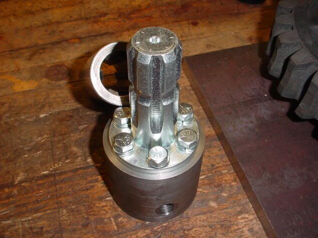
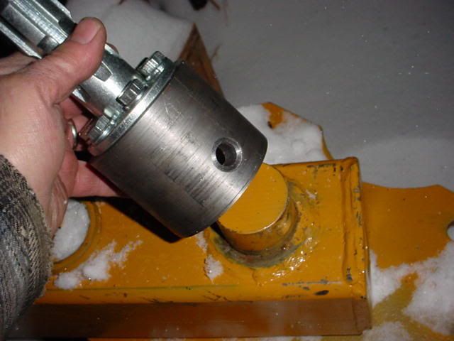
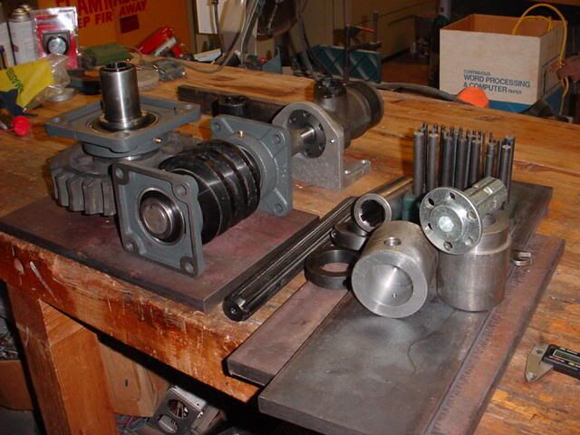
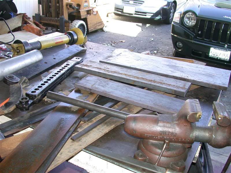
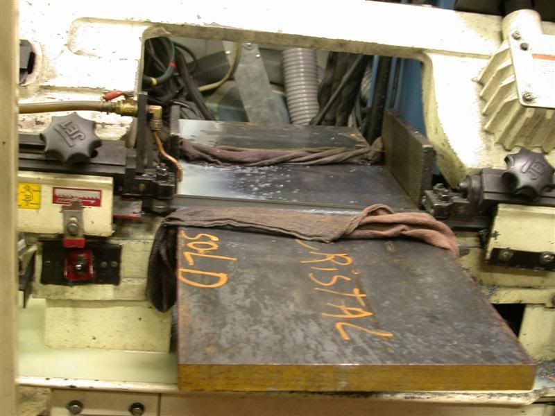
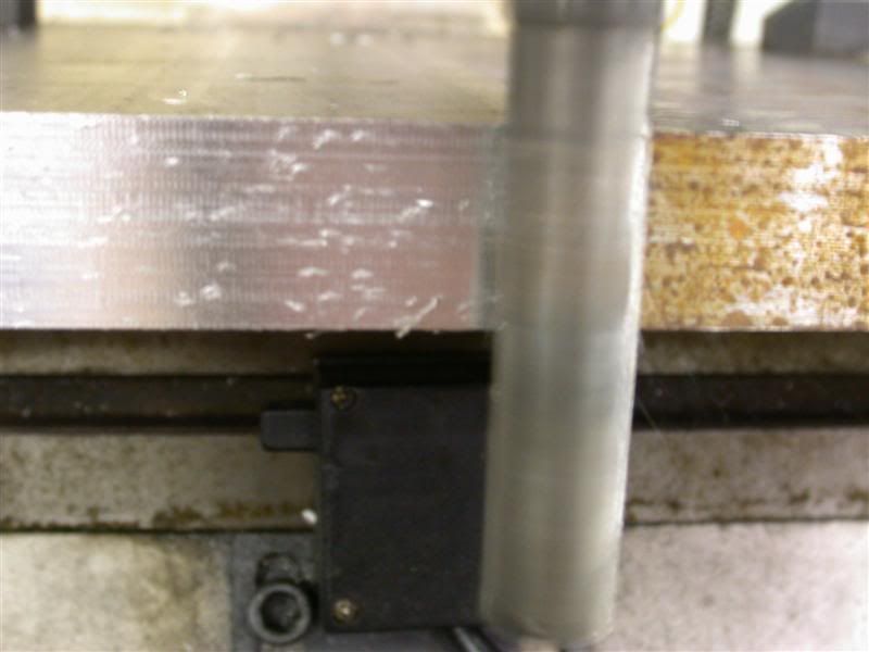
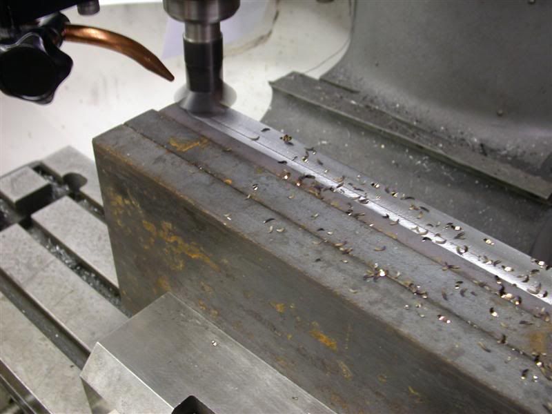
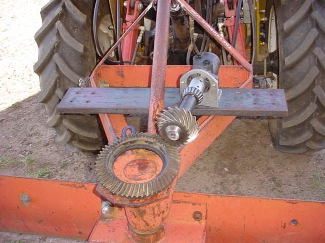
I've had the motor for a couple of years now from eBay. I have another just like it that I made into a TPH winch. The Ring & Pinion gear I salvaged out of an old rear-end I just happen to have laying around. I turned down the splined end of the shaft to 1" OD and cut a 1/4" key slot into it. I used a 1" keyed coupler to attach it to the motor. Man that metal was super hardened, it took a while to turn down and cut the key slot.


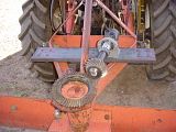
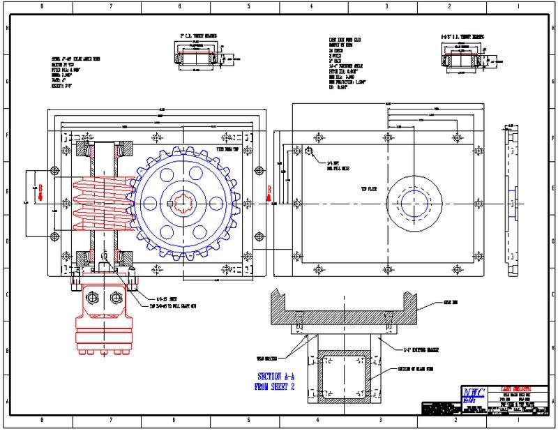
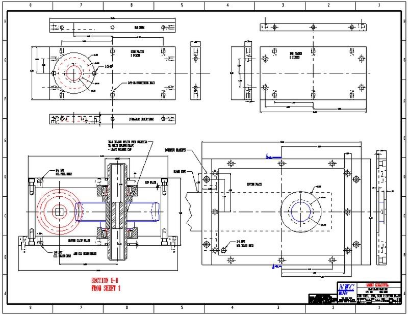
After careful consideration, I decided the basic idea of rotating the blade 360* was cool, but the gearing and the construction of the blade itself was not going to work, not at all.
I really want this in a bad way, so nothing is going to stop me.
 
   / 360* Rotating Back Blade Project
  • Thread Starter
#2  
I thought of all kinds of ways to do this – I even considered rigging up some sort of mechanism that is similar to how a steam locomotive moves a piston back & forth to cause a wheel to rotate 360* – sort of like this:

rodsmall.gif


But obviously that’s a “little” more complicated than I care to fabricate.
There has got to be a better way to do this. I did some more research and thought about a right angle gear box – but never found what I was looking for. Either too big, too small or would not hold the blade against all the forces etc, etc. I finally decided on a worm gear drive mechanism – now I am searching worms & worm gears. Again, I was having difficulty finding anything that was just right for my needs, the gears were just too small and the teeth would be ripped out by the first rock I hit. As a potential solution, I thought about this idea to get as many teeth engaged as possible with a smaller worm gear:

Here is the new design concept (virtual CAD) - a little busy but
I just might be able to fabricate it from mostly off the shelf items.


Nope - again too complicated for me to fabricate, and the chance for failure too great.
 
   / 360* Rotating Back Blade Project
  • Thread Starter
#3  
Back to the drawing board, as good luck would have it, I stumbled across Martin gears and found these gears. Check out this Worm & Worm Gear that I scored! They are massive, the hardened Worm is 4" long X 3" dia :eek:

The cast Gear is 2" thick X 8" dia it has 24 teeth and weighs 22 pounds.


I picked up a few 4 bolt flange bearings from Surplus Center.
These pic's are of laying out the assortment of parts to get an Idea of how it's all going to be assembled, and to get some rough measurements for steel plate I will need to tie it all together.


Somewhere in there you might notice a few hollow 1-3/8" x 6 spline PTO shaft couplers. Those are what I plan on using in the center of the worm gear that will couple to the back-blade.


In the far right is the hydraulic motor to drive the worm it’s a15 cu in/rev and with the flow from my tractors hydraulic pump it will turn in the neighborhood of 60 RPM.
With 24 teeth on the worm gear, I will get somewhere around 2.5 RPM at the blade.
I have one of the flange bearings setting on top of the worm gear to get an idea of how it will support the gear and PTO driving shaft coupler.


Larry
 
   / 360* Rotating Back Blade Project
  • Thread Starter
#4  
One thing that has to be done is to machine the inside of the worm gear. The ID is 1.5" and I need to bore it out to 2" dia then machine an internal key slot.

I chucked it to my lathe to see if it fits and turns true. The gear is much BIGGER than I imagined :eek:


Broaching the key slot(s) is something I have never done, so I'm not sure how that's going to work. I have milled key slots in shafts - that seems easy, but cutting a key slot inside ???

Fortunately the worm is already bored & keyed to the size I need :)


Larry
 
   / 360* Rotating Back Blade Project
  • Thread Starter
#5  
When completed, this is going to be a real convenience. I'm sure it's not cost effective and I will spend more time making it than the accumulative time spent getting on & off the tractor to make adjustments. But what the heck - I think this is a good project to keep me out of trouble.

The gear is huge and I was not exactly sure my lathe could handle it and had questions about cutting out the internal key slot. The gear was expensive and I did not want to mess it up royal.

I went over to seek the advice of my neighbor Herman, he’s a retired machinist. And I had to drop off his Oxy Acetylene tanks that I just got refilled for him. I brought the Worm Gear for him to look at- he was as happy as a clam! His lathe is much larger and was able to hold the Worm gear no problem, so he will bore it out from 1.5" to 2.0" And offered to cut the internal key slot! What a great offer, I have to work (travel all week) and Herman needs something to do. This is a win / win situation for both of us.

Larry
 
   / 360* Rotating Back Blade Project
  • Thread Starter
#6  
After I got back from my travels I stopped by to see what was happening, This is what Herman got done while I was gone:

He got the Worm gear bored out to 2" ID:


This 1-3/8 x 6 spline PTO shaft coupler is going to be keyed & installed inside the Worm Gear. Two of them will be welded together for the length needed.


Herman is making a tool to cut the internal key slot into the Worm Gear. He is explaining to me how it will work. He’s made these types of tools before to cut internal key slots.

 
   / 360* Rotating Back Blade Project
  • Thread Starter
#7  
Here's the home made “Red Neck” internal Key cutting “broach” :D

I just got back from helping him cut the key. It takes about 4-6 strokes per .002 depth of cut. It's slow going and man, my arms are about to fall off!

Herman said It's OK to laugh as hard as you want. We both got a real workout raising & lowering the spindle to make the cuts. :rolleyes:


Here is a closer view.


And a shot of the key-way in progress:


Larry
 
Last edited:
   / 360* Rotating Back Blade Project
  • Thread Starter
#8  
Here's my neighbor Herman :


And a short clip of the actual cutting process:


Larry
 
   / 360* Rotating Back Blade Project
  • Thread Starter
#9  
Well progress is slow - Sorry this is dragging out so long - I beg your patients please. I seem to be missing the super human machinist "Rob (3RRL) Gene" ;)

Good news is the key-way in the Worm gear is done! It came out nice and I am pleased.

I didn't want to use that 25 year old worn-out back blade for this project. (The one pictured in the very first post on this thread). Not only that, the way it was constructed did not lend itself easily to mount the right angle worm gear box that I am TRYING to make.

So - on my way back from a road trip to El Paso, TX, I stopped by Tumbleweed Equipment and picked up this brand spanking new back blade ;D I checked several styles out and this one is the ticket for what I want to do.

Here's the blade in pieces in the back of my company van.I took it apart so it would fit.
Check out the Ice Berg that fell out of my FEL bucket in the background!


This shows the swinging offset feature. Which will allow the blade to be adjusted to a position off center. I'll install a hydraulic cylinder to control the offset.


The blade and reversible cutting edge. Also shown is the main pivot point. It's 2" dia solid round - just what I was looking for to couple the gear box to.


Larry
 
   / 360* Rotating Back Blade Project
  • Thread Starter
#10  
That Ice Berg makes a real nice wheel chock ;)


Even though I took it apart, the pieces are heavy :p


Getting it unloaded was all I had time for, plus it's really cold out there.

Larry
 
 
Top