IH 3414 front valve bank disassemby.. Weak or No hydraulic? This may be the solution!

   / IH 3414 front valve bank disassemby.. Weak or No hydraulic? This may be the solution! #1  

thetester

Bronze Member
Joined
Oct 26, 2013
Messages
55
Location
Benton MS
Tractor
3414 IH
Ok guys, this post will be a picture heavy illustration of my disassembly of the front valve bank on my International Harvester 3414.My machine just so happens to be a bc144 english gas burner.. I am also posting this as quest for help and suggestions.. I know there are few posts floating around that actually help or answer the questions regarding hydraulic issues with these machines.. I have seen many suggestions but never a solution or problem solved.. I dug off into my machine and took plenty pictures.. I thought why not go back to the roots of what the web is all about and post it up FREE for everyone to see what I found.

In no way is this professional or complete.. It is simply my findings and how I went about taking my valve bank apart, what I found and think to be everyones issue with these old machines..

After a gazillion times trying to post MANY pictures and info I figured out two things about this site.. One, this is a GREAT site to get information you need on just about any tractor and number two is it sucks being the person trying to POST that information.. It takes a while to try and create a proper post with informative pictures and text.. This sites gives you a time limit thus making it VERY VERY hard to create a long or big post.. In any case I am going to start posting smaller tid bits and draw the whole thing out into many posts.. Please let me finish up all my posts before you reply or ask questions or give me advice..

Thanks
 
   / IH 3414 front valve bank disassemby.. Weak or No hydraulic? This may be the solution!
  • Thread Starter
#2  
LOk, I purchased this old 3414 Bc144 gas burner for about $1500, got her home and started digging. Well not long after I noticed that it was awful weak.. I started to ask questions on the internet and read other posts where TONS of folks where having the same issue.. I could start it up cold and the hydraulics would work for a time or two then go weak.. I could turn it off start it back up and same thing the loader would work up and down a couple of times then stop... Dangdest thing I had seen and thought well I got something sticking open or closed somewhere.. I also found that if I pushed up or down on the front loader lever while operating the backhoe then pressure would build and operate the hoe.. HMMMMM Every single post I find seems to be the same issue with these models..

Well, I guess most folks decided to either give up, send their banks off for repair or find the problem fix it and never post back up what they had found.. So I decided to dig off into mine and find the problem.. I figure I would do exactly what the internet is for and post what I found back up FREE for everyone.. However much its worth I hope it helps some guy out there. I know it would have me in the beginning..

Disassembly of the FRONT valve bank..

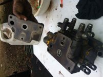
Here is the first plate taken off the assymbly.. The only thing I have to say here is that my Orings were hard and flat.. I used Nitril Orings as replacements and hopefully they will not deteriorate over time.. I replaced these from a pack of nitril Orings I had.. At the time I did not have part numbers for originals and the standard size Orings seem to fit pretty well as in thickness and size.. When you go to put your stack back in be sure to use something to "stick" the orings in place as they like to fall out and its hard or impossible to tell if thats happend cause things are so heavy awkward when putting the bank back in.. I used a little grease.
IMG_1899.jpg

Here is a 2000 P.S.I Pilot relief
IMG_1900.jpg
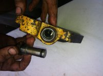
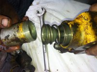
Here I am starting on the second stack. There are little very THIN aluminum covers with hex heads on them.. Hopefully yours comes off with a socket.. Mine DID NOT!! The socket head wanted to round and I didn't want to ruin the cap.. I figure better find another way so I can use the hex head in the future when the cap isn't stuck.. For me I related back to my gunsmithing knowledge and used two wood blocks with V grooves cut in them. I coated the grooves librally with pine rosin and clamped them over the tube.. Took some muscle but it gave in..
IMG_1901.jpg
 
   / IH 3414 front valve bank disassemby.. Weak or No hydraulic? This may be the solution!
  • Thread Starter
#3  
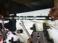
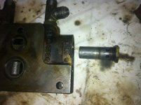
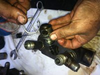
Here I have laid the control valve body out for you to see as reference if you have never taken yours out before. Be extremely careful when you take the rod out as there are three little ball bearings that can get lost VERY easy.. I almost did not find one of mine and thank god for neodenium magnets.. Do this is a clean open area where if things fall you will find them..
IMG_1902.jpg
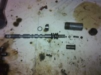
here I laid things out sorta in order.. You can see those ball bearings I am talking about.. Careful getting that Oring off too as the edges of the valve body is very sharp and cut the Orings with ease.. Same thing with puting it back in.. I found it easy to rotate the rod and keep it dead straight lubed with plenty of grease.. It was real snug but it went in fine..
IMG_1909.jpg

Here is a closer view of the bearings and assembly
IMG_1910.jpg
 
   / IH 3414 front valve bank disassemby.. Weak or No hydraulic? This may be the solution!
  • Thread Starter
#4  
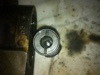
Here I removed the "CUSHION" relief is is marked on the hex head 1600 P S I as that is what the parts break down refers to it as.. It has one set of holes at the base and if you look you can see a ball bearing in orifice..
IMG_1911.jpg

Here is the top view of the orifice..
IMG_1912.jpg
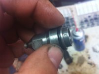
Ok now to spare room I did not show the picture of this removed.. It is a 2000 p s i pilot relief valve.. Notice the two sets of holes at the base.. In case yours don't have numbers it may help you keep things straight.. Now this thing can be taken apart.. No not that it is suppose to but it CAN and so can the cushion valve.. If you look close on the sides of the valves they are " staked " it looks like spot welds but it is where compression was used to create an indention to retain the proper adjustment on the valve.. Welllllll if you slightly pry out on the sides a little but not to much (it appears to be a little brittle), you can unscrew orifice pilot..

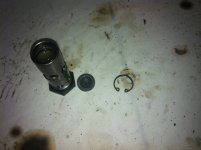
On this one it had a snap ring
IMG_1918.jpg
You can see on the pilot valve it has a very tiny hole for the orifice.. Mind the Oring on the outside. Same here I replaced with standard Orings..
IMG_1919.jpg
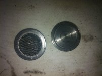
On the back side of that orifice is a tiny stainless screen.. Mine was clogged like the dickens.. It had rubber and all kinds of gunk in it.. Surely it will effect the power of the hydraulics and if your machine is like most I have read about people have removed the hydraulic filter making things worse.. this little screen gets it bad.. It would be a good thing to keep in mind just where this valve is when you put things back as when things start to bog down in the future you can locate it and remove the right valve the first time and check this filter..
IMG_1922.jpg
 
   / IH 3414 front valve bank disassemby.. Weak or No hydraulic? This may be the solution!
  • Thread Starter
#5  
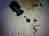
Ok now underneath the orifice will be the screen an beneath that a spring now we come to this part of the valve.. It sorta floats and rides up and down inside the pilot valve body.. Keep in mind which way it comes out as I suppose someone COUUULD actually reverse it.. Notice the "staking" yes that little crack was already there.. In the body below is a pilot screw ( that is what the staking you see in the picture below retains in place) When you unscrew the pilot KEEP TRACK OF HOW MANY TURNS IT TAKES TO TAKE IT OUT!! Mark it, scratch it, dykem it something and write it down..
IMG_1924.jpg

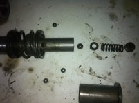
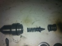
Here it is all laid out as it comes out.. Notice the pillot screw with the Oring on the right... This is what you keep track of when you remove it..
Ok now if you look there is a little conical shaped plunger sitting in the spring (since I do not have proper diagram and these are not supposed to be taken apart I use my own terminology) if you know the proper name for this piece then great.. For the sake of explanation in this illustration its a conical plunger LOL.. This piece was badly galled and beat up from the many times its been slammed into the hole its closes.. Thankfully I am a machinist and own my own shop.. I simply machined another one from carbon steel..
IMG_1925.jpg

here is a view of how it fits inside the pilot valve body when it is assembled..
IMG_1921.jpg
 
   / IH 3414 front valve bank disassemby.. Weak or No hydraulic? This may be the solution!
  • Thread Starter
#6  
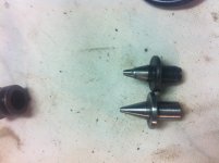
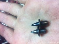
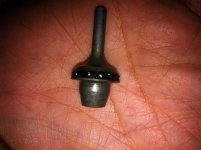
Here is a close up view of the "conical plunger" that is damaged next to the new machined part.. I mentioned that I had machined it out of carbon steel.. I know some might suggest tool steel.. I know buuuut when I took a file to the old one it actually bit in.. It didn't skate off like a typically hardened part.. actually it seemed to be slightly unhardened if that makes sense to any non metal workers.. To a machinist you can sorta tell where the hardness is at when your working with metal.. Since so it gave me the bright idea I could make another from the material on hand..
IMG_1926.jpg

After I had machined the new one I hardened my new part at approx 450 degrees F or deep straw yellow.. "Chisel hard"
IMG_1929.jpg
 
   / IH 3414 front valve bank disassemby.. Weak or No hydraulic? This may be the solution!
  • Thread Starter
#7  
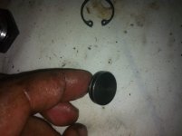
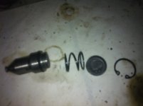
Ok now for the culprit that I think is causing everyone the grief.. It is called a check poppet assembly.. If you look on the bottom of your valve bank you will see a plug that is held in by a snap ring.. You can see the size below.. ON the front bank there are TWO for this purpose I only illustrate disassembly of one..

IMG_1903.jpg

You can see how it came out of the bank.. The poppet stem sits inside the retainer as so the tapered end seats against the retainer.. On the poppet there is a rubber ring.. To ME this appears to be made on the poppet. I did remove the old cracked deteriorated rubber.. It appeared to be glue on the poppet where the rubber came off.. The ring on the poppet itself was flat unlike a typical Oring groove.. This made me believe that it was made on from the factory with some type of adhesive.. This is just my opinion I have no idea. I DO know that that I can NOT locate the poppet anywhere... If you think about it the "trick" of raising up or down on the loader lever to operate the hoe worked because the valve body rod was acting as a blockage.. when you would pull the lever half down the rod was in between the passages in the rod and bank itself.. These poppets cant close fully and its bypassing fluid around where the rubber is..
IMG_1904.jpg
Here you can see a close up of the rubber on the poppet.. It is all crumbly and falling apart.. I can't quite think of why the machine worked for a couple of lifts of the front bucket when cold or first cranked up. I do know it WAS the problem... I replaced the rubber with a snuggly fit metric Oring.. I figured it would work for a while.. I knew it would fail but I figured it would get me through a job I had for the hoe.. Wellllll it actually got me only about 5 to 15 mins into the job before it failed.. The simple Orings just wont stay on and the pressure from the hydraulics cut and break a regular Oring..
IMG_1907.jpg
 
   / IH 3414 front valve bank disassemby.. Weak or No hydraulic? This may be the solution!
  • Thread Starter
#8  
I am going to further give you guys a parts break down part numbers.. I guess a few of you already bought a catalog on ebay "RIPOFF" and or really need the part numbers because the guys at CASE or KOMATSU had a really hard time helping me.. The break down is in PDF format and free to download here..
Code:
http://www.scribd.com/doc/220196381/3414-HYDRAULIC-PART-NUMBERS
I did not create a hyperlink as I did not know this sites policy.. I simply put it in code so not to link..

The PDF was to large to upload here so I uploaded a copy of all part numbers and parts diagram for the front valve bank on scribed.. This is information that is freely available as should be!! The repair manuals that are all over ebay should be free as well.. That publication is far ran out on copyright im sure and most of the copies on ebay are just that copies.. Matter of fact the gentleman sent me one for free via email and for free in PDF format.. To my knowledge it seems stupid to charge someone for a parts catalog with part numbers just to buy YOUR parts.. Never seen before I dealt with this 3414..


If anyone has ANY idea where to buy the poppets please reply and let me know.. If I cant find one in the next week I am simply gonna machine a solid poppet and see if that will work.. I will post my results back here.. I am also going to post a disassembly of the hydralaulic pumps with plenty of pictures. I have even more information on the setting of the gas carburetor and where to get a brand new one that is almost identical to the original for the BC144.

Please feel free to reply with any information

Thanks guys and hope this helps someone!!
 
   / IH 3414 front valve bank disassemby.. Weak or No hydraulic? This may be the solution! #9  
Hello:
I just purchased a 3414, and 1 of the issues I noticed is the aluminum tube is cracked off flush to the valve body, I tried to pull the tube off, but it will not move. Am I missing something here or is it stuck and I am not pulling hard enough.
Thanks, your post is very helpful
 
   / IH 3414 front valve bank disassemby.. Weak or No hydraulic? This may be the solution!
  • Thread Starter
#10  
Hello:
I just purchased a 3414, and 1 of the issues I noticed is the aluminum tube is cracked off flush to the valve body, I tried to pull the tube off, but it will not move. Am I missing something here or is it stuck and I am not pulling hard enough.
Thanks, your post is very helpful

Hi wagonboy,, if you refer to post number two you can see that "if what I'm taken what your saying correctly" that aluminum tube is threaded. If it is broke off it's gonna be all kinds of fun getting the remainder out. If somehow unscrewing the remainder is impossible, what I would do is take the valve body out. Take a small needle file "$3.00 from harbor freight whole set" and file a cut groove across the remaining tube. You would be able to take a flat head screwdriver and peel the rest of the aluminum tube up and off of the threads.

These tubes are needed to keep debris out and away from the valve. I hope you can locate another. If not I can possibly machine you another replacement out of metal. The aluminum tube diameter is odd and it's to costly machining a tube from a solid bar of aluminum. I can machine it for about $30 bucks and you pay flat rate shipping. Pm me if I can help!

Thank you and glad my post helped.
Thetester!!
 
 
Top