3RRL
Super Member
- Joined
- Oct 20, 2005
- Messages
- 6,825
- Tractor
- 55HP 4WD KAMA 554 and 4 x 4 Jinma 284
I know there are many threads about setting the valve lash and torquing the head bolts by now, but this one is for Loretta's 2008 Jinma 284 with the QC395T EPA conforming engine. Loretta helped me with the whole procedure and did several things herself.
It might help some guys who have that engine?
Prior to that, I recommend a few safety precautions and set up the tractor the night before so the engine is "cold" or ambient temperature when doing this adjustment.
-Transmission in neutral.
-Set parking brake.
-Move the fel and bucket up and out of the way and prop it up with restraints.
-Turn off the fuel.
-Pull the "kill switch" out and hold it back with vice grips.
-Disconnect the ground at the battery terminal, not the frame.
You don't want to "accidentally" start the tractor.
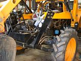
I don't know about you guys, but I found it extremely difficult to get in there to do any wrenching. Everything is so much smaller and tighter than my Kama 554. Even trying to take off the alternator shield was undoable for me (couldn't get to the bottom bolt). I was planning on tightening the alternator belt and use that nut to turn the crankshaft, but couldn't do it that way. I had the bucket resting on the toothbar and the fel partially up, but I would recommend having it all the way up and propped/lock up there so you can move around better.
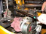
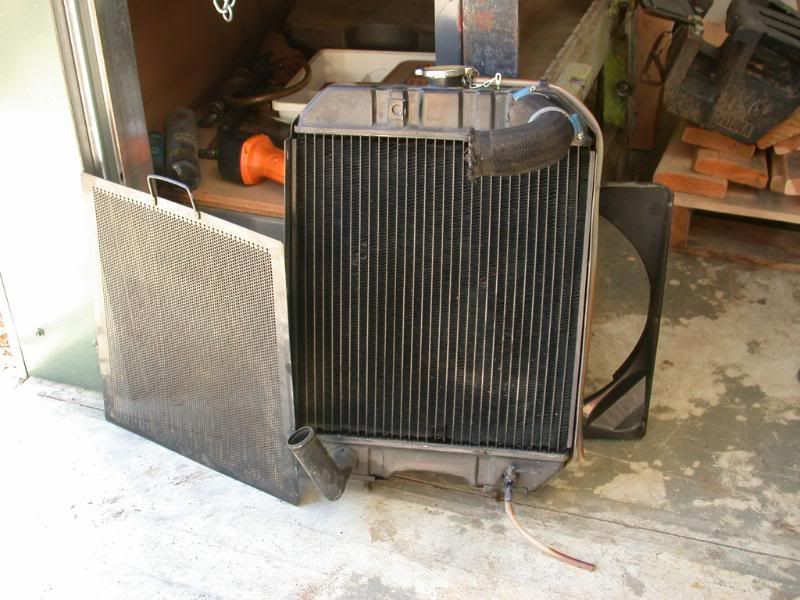
Since it was so cramped and tight to get to the nuts and bolts, I started by taking off the power steering and air filter bracket. Remove the air hose to the filter. Then I drained the radiator and removed it. Loretta had a chance to thoroughly clean it while it was off.

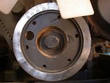
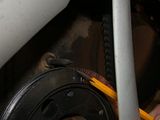
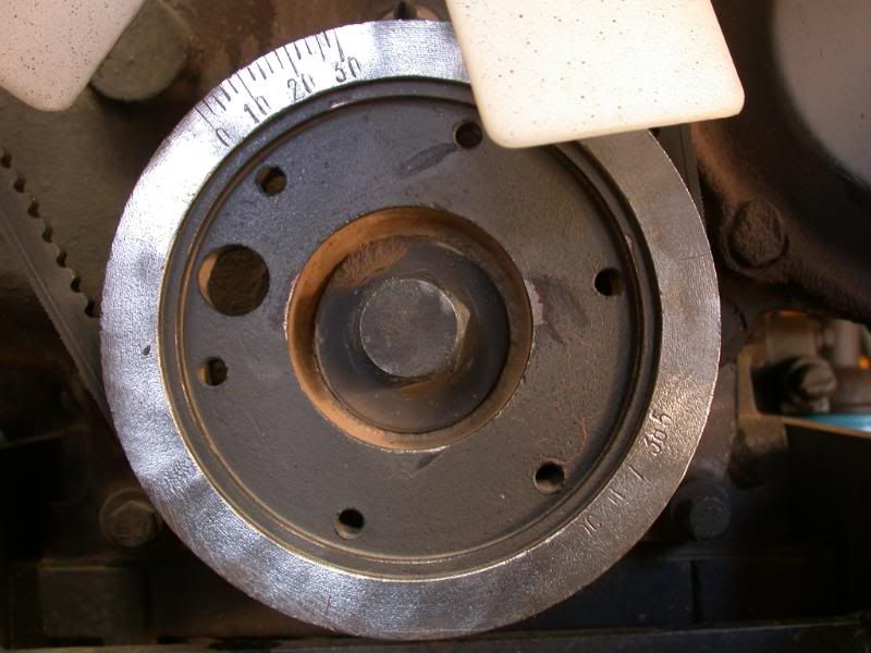
Once that was out of the way, I cleaned off the front of the crankshaft pulley to reveal the timing marks on it to find top dead center as per the instructions in the manual. You can verify the marks by removing the inspection cover that exposes the flywheel and there are corresponding marks on it too. I was able to use a large wrench right on the crankshaft pulley nut to rotate the engine.
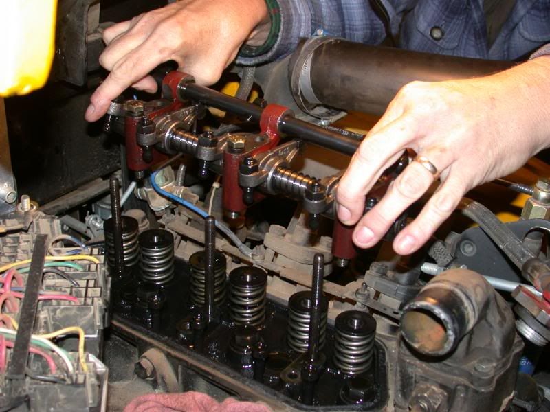
I removed the fuse box to get it out of the way and then the valve cover to expose the valves. But first, I disconnected the compression relief lever at the back of the valve cover, nearest the cab. In order to re-torque the head bolts (8 of them) you have to remove the rocker shaft assembly. Remove the nuts (3) and bolts (3) evenly since it is under pressure from the valve springs. Then lift the assembly off and put it in a clean place. You will replace it in the same fashion when setting the valve lash later.

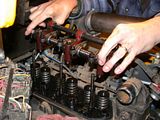
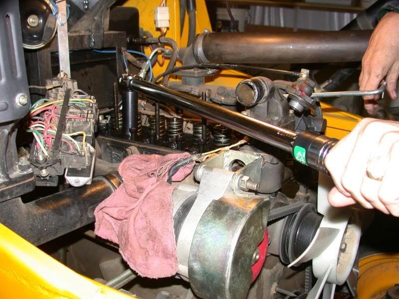
Then you can get a good torque wrench in there to re-torque the headbolts. There are several thoughts of how to do this. Some guys loosen them up, clean and then re-torque. I personally only re-torqued them, not loosening them first. My thoughts are they only need to be tight per spec and I don't want to ruin a head gasket accidentally. I found only 2 head bolts that moved. I used 125 ft/lbs on the torque wrench. Her manual calls out 150-170Nm. (110-125ft/lbs)
Ok, so now you can replace the rocker shaft assembly. On Loretta's tractor, I noted when removing the nuts and bolts from the shaft assembly that they were not very tight. In re-torquing those, I only used 36ft/lbs (50Nm) because I was afraid to strip them. I know some guys use more than that, but since they were not even that tight when I took them off, I decided to use that figure.
Anyway, then you can get to adjusting the intake and exhaust valves on each cylinder.
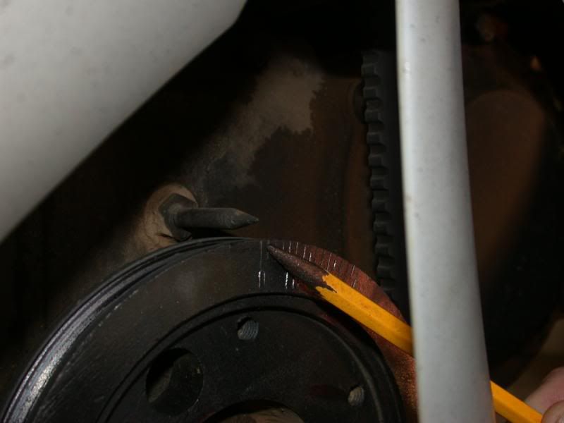
Start by finding top dead center on cylinder #1, which is nearest the radiator. The manual says to line up the "O" mark on the crankshaft pulley with the pointer. On her engine, the valve closest to the the radiator is the intake valve and the one next to it is the exhaust valve. You can verify this by rotating the engine to see the how the valves work. Rotate the engine clockwise looking from the front of the tractor. The vanes on the radiator fans will help you verify that too. When you rotate the engine so that intake valve just starts to close, and just before the exhaust valve just starts to open, that's top dead center. After "eyeballing" the valves, I checked the crankshaft "O" markings and, indeed, it lined up with that position, and also the flywheel mark to make sure ... it all lined up.
Plus, that is exactly what her instructions in the manual said to do.
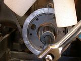
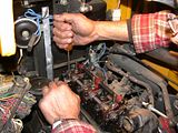
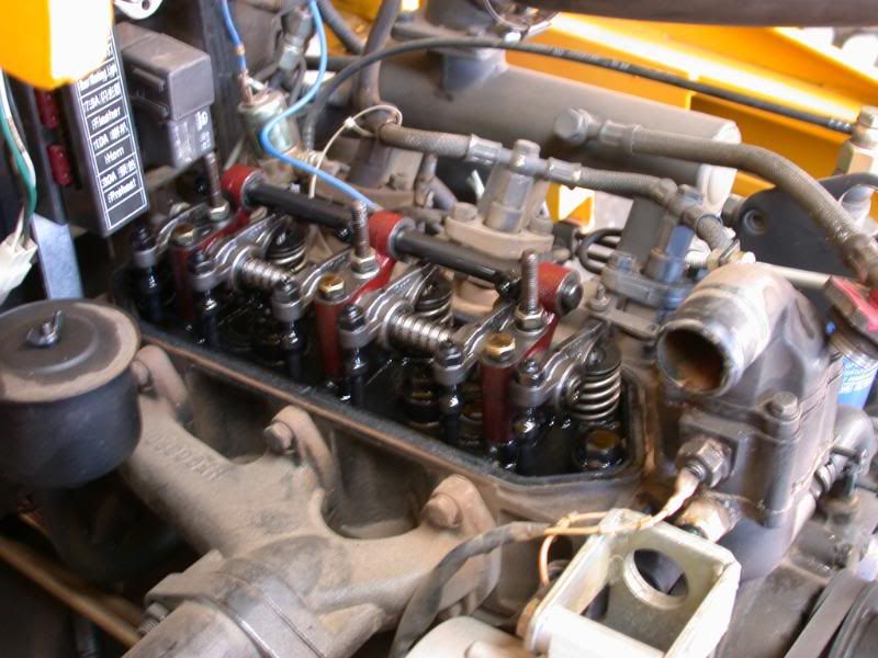
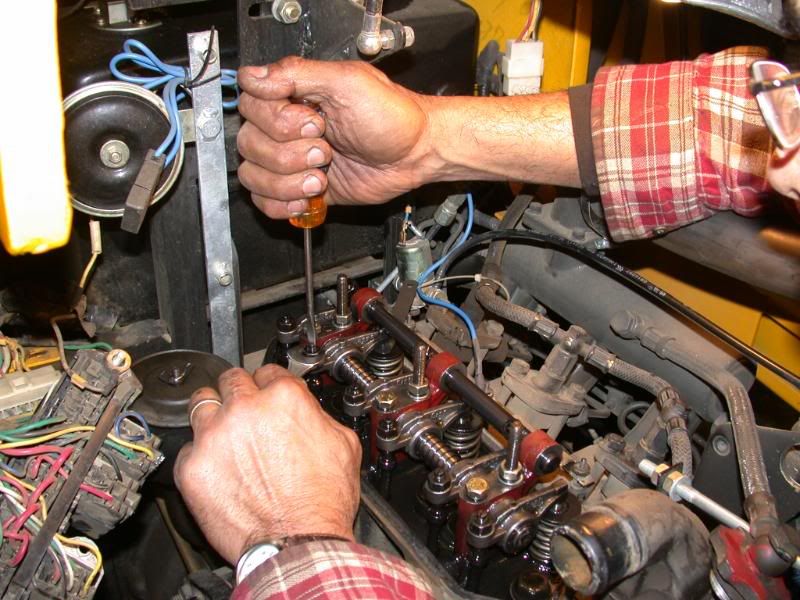
Then you can set the valve lash on both intake and exhaust valve for cylinder #1. Loosen the nut above the push rod and adjust the gap between the valve stem and rocker arm. Use a screw driver to adjust the rod until you feel the feeler guage slide smoothly in between. Hold the screw driver steady and re-tighten the locking nut and re-check the gap. Her manual called out 0.20-0.25mm (.008"-.010") for the intake valve clearance. I used the middle tolerance and used a 0.23mm feeler guage. The exhaust clearance is called out at 0.25-.030mm (.010"-.012") so I used a 0.28mm feeler guage.
After setting cylinder #1, rotate the crankshaft 240 degrees clockwise and do cylinder #3, which is the one nearest the cab. Then rotate another 240 degrees to do cylinder #2 (in the middle). That is the firing order on this engine. Each time the crankshaft was rotated, the pointer lined up with another mark on the crankshaft pulley as well. So we were on the right track.
When you're done, put everything back together again. I had a re-usable rubber valve gasket but you might a new one or need to make one. So be prepared for that. when you replace the valve cover, be sure to check if the little coupler for the compression relief lines back up. You can check it by moving the compression relief valve (once the valve cover is back on) by feeling the shaft rotate through the oil fill hole on top of the valve cover. You can see where the feeler guage is in the photo and how to adjust the valves with screwdriver and wrench.
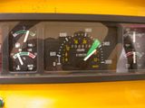
Also, before I removed the rocker shaft assembly I had checked the valve lash first and all the valves were super tight. I mean really tight like I could barely get a .003" feeler guage in there! Some were net and NONE of them were loose! Maybe that's why she could never rev the engine up to high rpms. She would always come up just short of the green zone, or about 2100 rpm max before. I was hoping this valve adjustment would help that.
I started the tractor and let it warm up a bit. It was noticeably clacking a little more than before, just like my Kama did. Then I reved it up and it went right past the green zone, in fact right to 2400rpm right on the nose.
I followed the instructions in the manual and it must be alright since the results were good.
Rob-
It might help some guys who have that engine?
Prior to that, I recommend a few safety precautions and set up the tractor the night before so the engine is "cold" or ambient temperature when doing this adjustment.
-Transmission in neutral.
-Set parking brake.
-Move the fel and bucket up and out of the way and prop it up with restraints.
-Turn off the fuel.
-Pull the "kill switch" out and hold it back with vice grips.
-Disconnect the ground at the battery terminal, not the frame.
You don't want to "accidentally" start the tractor.
I don't know about you guys, but I found it extremely difficult to get in there to do any wrenching. Everything is so much smaller and tighter than my Kama 554. Even trying to take off the alternator shield was undoable for me (couldn't get to the bottom bolt). I was planning on tightening the alternator belt and use that nut to turn the crankshaft, but couldn't do it that way. I had the bucket resting on the toothbar and the fel partially up, but I would recommend having it all the way up and propped/lock up there so you can move around better.
Since it was so cramped and tight to get to the nuts and bolts, I started by taking off the power steering and air filter bracket. Remove the air hose to the filter. Then I drained the radiator and removed it. Loretta had a chance to thoroughly clean it while it was off.

Once that was out of the way, I cleaned off the front of the crankshaft pulley to reveal the timing marks on it to find top dead center as per the instructions in the manual. You can verify the marks by removing the inspection cover that exposes the flywheel and there are corresponding marks on it too. I was able to use a large wrench right on the crankshaft pulley nut to rotate the engine.

I removed the fuse box to get it out of the way and then the valve cover to expose the valves. But first, I disconnected the compression relief lever at the back of the valve cover, nearest the cab. In order to re-torque the head bolts (8 of them) you have to remove the rocker shaft assembly. Remove the nuts (3) and bolts (3) evenly since it is under pressure from the valve springs. Then lift the assembly off and put it in a clean place. You will replace it in the same fashion when setting the valve lash later.
Then you can get a good torque wrench in there to re-torque the headbolts. There are several thoughts of how to do this. Some guys loosen them up, clean and then re-torque. I personally only re-torqued them, not loosening them first. My thoughts are they only need to be tight per spec and I don't want to ruin a head gasket accidentally. I found only 2 head bolts that moved. I used 125 ft/lbs on the torque wrench. Her manual calls out 150-170Nm. (110-125ft/lbs)
Ok, so now you can replace the rocker shaft assembly. On Loretta's tractor, I noted when removing the nuts and bolts from the shaft assembly that they were not very tight. In re-torquing those, I only used 36ft/lbs (50Nm) because I was afraid to strip them. I know some guys use more than that, but since they were not even that tight when I took them off, I decided to use that figure.
Anyway, then you can get to adjusting the intake and exhaust valves on each cylinder.
Start by finding top dead center on cylinder #1, which is nearest the radiator. The manual says to line up the "O" mark on the crankshaft pulley with the pointer. On her engine, the valve closest to the the radiator is the intake valve and the one next to it is the exhaust valve. You can verify this by rotating the engine to see the how the valves work. Rotate the engine clockwise looking from the front of the tractor. The vanes on the radiator fans will help you verify that too. When you rotate the engine so that intake valve just starts to close, and just before the exhaust valve just starts to open, that's top dead center. After "eyeballing" the valves, I checked the crankshaft "O" markings and, indeed, it lined up with that position, and also the flywheel mark to make sure ... it all lined up.
Plus, that is exactly what her instructions in the manual said to do.
Then you can set the valve lash on both intake and exhaust valve for cylinder #1. Loosen the nut above the push rod and adjust the gap between the valve stem and rocker arm. Use a screw driver to adjust the rod until you feel the feeler guage slide smoothly in between. Hold the screw driver steady and re-tighten the locking nut and re-check the gap. Her manual called out 0.20-0.25mm (.008"-.010") for the intake valve clearance. I used the middle tolerance and used a 0.23mm feeler guage. The exhaust clearance is called out at 0.25-.030mm (.010"-.012") so I used a 0.28mm feeler guage.
After setting cylinder #1, rotate the crankshaft 240 degrees clockwise and do cylinder #3, which is the one nearest the cab. Then rotate another 240 degrees to do cylinder #2 (in the middle). That is the firing order on this engine. Each time the crankshaft was rotated, the pointer lined up with another mark on the crankshaft pulley as well. So we were on the right track.
When you're done, put everything back together again. I had a re-usable rubber valve gasket but you might a new one or need to make one. So be prepared for that. when you replace the valve cover, be sure to check if the little coupler for the compression relief lines back up. You can check it by moving the compression relief valve (once the valve cover is back on) by feeling the shaft rotate through the oil fill hole on top of the valve cover. You can see where the feeler guage is in the photo and how to adjust the valves with screwdriver and wrench.
Also, before I removed the rocker shaft assembly I had checked the valve lash first and all the valves were super tight. I mean really tight like I could barely get a .003" feeler guage in there! Some were net and NONE of them were loose! Maybe that's why she could never rev the engine up to high rpms. She would always come up just short of the green zone, or about 2100 rpm max before. I was hoping this valve adjustment would help that.
I started the tractor and let it warm up a bit. It was noticeably clacking a little more than before, just like my Kama did. Then I reved it up and it went right past the green zone, in fact right to 2400rpm right on the nose.
I followed the instructions in the manual and it must be alright since the results were good.

Rob-
")