Jinma254 Alternator swap to Delco 10si, old regulator wiring???

   / Jinma254 Alternator swap to Delco 10si, old regulator wiring??? #1  

tigers2007

Silver Member
Joined
Apr 17, 2010
Messages
126
Location
Michigan
Tractor
John Deere AMT626, New Holland LS45
I just finished building my new "harness" to accomodate my soon-to-be installed 10si alternator. What a know is that of the three wires that go to the chinese alternator, two go to the external regulator and one goes directly to the ammeter and then to the fuse box (the red heavy gauge one).

From the regulator, according to the diagram, it then goes to the fuse panel. Can someone shed more light on that circuit? I might be understanding this wrong but here is how I think the regulator system works. The regulator "regulates" by taking a reference of the voltage of the wire that comes from the fuse panel to the regulator and then "controls" the alternators output. Does that sound correct?

Here is my issue and maybe I'm making a big deal out of this, but as I am wiring up my new 10si alternator, I see that from the two-prong plug on the side, one wire goes to the main (+) post and one wire must go to a "trouble" light. I'm curious if I could utilize the wire that already goes from the regulator to the fuse box AND then from the fuse box go to a panel light.

To keep it simple I suppose I could just avoid it all and just run it to a 12v panel light of my own drilled into the dash but I'm trying to utilize what is already there.

One more thing -- should I upgrade the old power wire (labeled #4) that hooks to the alternator?

On my custom build alternator harness I already have an 8gauge wire going directly from the alternator to the starter's huge (+) cable. ----> would that in itself affect the reading on the ammeter???
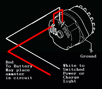
 
   / Jinma254 Alternator swap to Delco 10si, old regulator wiring??? #2  
are you talking about th old chevy alternator with built in reg.If so I think the big red goes to starter or battery.the two prog conector thats labeled 1 and 2 on the alternator.number one going to amp meter which goes to the key and number 2 goes to power source.Thats how I wired my old chevelle from external reg generator to internal reg alternator
 
   / Jinma254 Alternator swap to Delco 10si, old regulator wiring??? #3  
As you can probably tell from your diagram, wire 9 is regulator ground. Wire 8 connects to the alternator field post. Wire 4 connects the B+ post to the ammeter. It wouldn't hurt for that one to be 10ga. But if you do that, you should also upgrade the subsequent wire from the ammeter to the keyswitch to 10ga as well. Probably a good idea to replace the 3rd ammeter wire too, the one to the 30A system fuse.

But I thought the 10Si was considered a 1-wire alternator? What purpose will be served by wiring in the OE regulator as well? Or have I misunderstood something?

Regardless, it's actually the voltage regulator that sends (a regulated) 12v to the respective fused circuits. But the battery charge circuit has to bypass the regulator. Reason for that is, the battery needs MORE than 12v to recharge. In the case of charging, it's actually the battery that regulates the alternator output. The lower the battery, the more it pulls from the alternator - diminishing till it hits full charge.

The way the Jinma's wired up, you're going to lose some of that charging voltage through the wiring harness. What I did to mine was run an additional 10ga wire from the alternator B+ post to the starter end of the battery cable. That makes for a dedicated charging circuit, guaranteed to deliver everything the battery's askin' for.

//greg//
 
   / Jinma254 Alternator swap to Delco 10si, old regulator wiring???
  • Thread Starter
#4  
Mine is a 3-wire. I opted for this as I didn't want to have to high rev my engine to "excite" the alternator as with the 1-wire versions.

The custom harness I build has a 8g wire going from the (+) post to the (+) post on the starter that has the huge cable to the battery. I will keep the old wire in the (+) circuit as I've added it to the harness.
Will that have an impact on what I see on the ammeter due to the fact that I have the 8g wire going directly from the alternator to the battery?

"number one going to amp meter which goes to the key "

Are you sure about this? Its my understanding that if there is a fault with the 10si internal regular, it will automatically ground out Pin-1 to complete the warning light circuit (other end is wired from a key switched positive then to the postive terminal of a warning light bulb).
 
   / Jinma254 Alternator swap to Delco 10si, old regulator wiring???
  • Thread Starter
#5  
This diagram below says that the Pin 2 can go to the ammeter.

alt.gif


I don't like the idea of putting the Pin 1 wire to the ammeter as if it "grounds out" it will cause a short circuit as the ammeter is in-line with (+) circuit.

***Okay I just got clarification about the Pin 1. It is indeed a "Grounded" (-) wire UNTIL the alternator generates enough juice --- then it outputs (+). That would mean that the warning light would be ON if the alternator isn't putting out enough juice (as determined by the regulator). When it puts out enough juice, the warning light would extinguish.
 
   / Jinma254 Alternator swap to Delco 10si, old regulator wiring??? #6  
I will keep the old wire in the (+) circuit as I've added it to the harness.
Will that have an impact on what I see on the ammeter due to the fact that I have the 8g wire going directly from the alternator to the battery?
That "old wire" is the one I recommended you upgrade to 10ga.

But no. As long as the "old wire" (or 10ga upgrade I suggested above) still connects the B+ post with the ammeter - and as long as you maintain the 3 wire configuration - the extra charging wire will have no impact on indicated ammeter values. Converting to 1 wire however - and keeping the extra charging wire - will affect the ammeter reading significantly. Not completely, there's still be some positive and negative movement. But not to scale.

//greg//
 
   / Jinma254 Alternator swap to Delco 10si, old regulator wiring??? #7  
If you go with the one-wire setup it will take the ammeter out of the loop altogether. I removed the ammeter and installed a voltmeter in it's place - it will give you almost identical info except for the rate of discharge.
 
   / Jinma254 Alternator swap to Delco 10si, old regulator wiring??? #8  
By having a wire from the alternator output connected to the starter solenoid, and the existing wire going to the panel your ammeter will not work. Your wiring will short the ammeter, causing it to always read zero.

As you probably know, your alternator has an internal regulator, so you need to remove the original regulator.

You need to have switched 12V going to terminal 1. You are correct that it will go to ground if the alternator should stop working, lighting the bulb.

The above about the regulator sending regulated power to the fused circuits is absolutely wrong.

The regulator send current to the alternator field winding, controlling the output of the alternator.

The alternator should send power to the load side of the ammeter. The ammeter only shows the flow of current in and out of the battery. If the battery needs charging and current is flowing from the ammeter in to the battery the needle will move in the + direction. If the electrical load ( lights etc) is more than the alternator can supply, the extra current is drawn from the battery and the meter moves in the - direction. When the alternator is putting out enough current to meet the needs, and the battery does not require charging, the ammeter will read zero.


Stan
 
   / Jinma254 Alternator swap to Delco 10si, old regulator wiring???
  • Thread Starter
#9  
Well I have everything wired up correctly - I chose to just install a warning lamp on the dash.

I have read here and other places that the 10si is an easy swap. The easy part must have something to do with a special bracket? I just noticed that I will need a new bracket as the old one is not even close.

How did you guys make this work? Should I go nuts with the welder and make my own bracket or am I missing something here?

I tried moving the bracket piece to a different location on the hydro pump and it is too short. People make it sound so easy on the other forums, i.e. "easy install. it slides right in", etc.
 
   / Jinma254 Alternator swap to Delco 10si, old regulator wiring??? #10  
By having a wire from the alternator output connected to the starter solenoid, and the existing wire going to the panel your ammeter will not work. Your wiring will short the ammeter, causing it to always read zero.
That's not what I described. Read my post again, TIGER has stated he wants a 3 wire configuration here. The extra charging wire goes from the alternator output (B+) to the starter end of the + battery cable. All that does is parallel charging voltage to the battery. My 3 wire tractor has been wired this way for years: full alternator output charges the battery - ammeter deflection IS NOT AFFECTED. My other tractor on the other hand, has had a 1-wire conversion, plus the extra charger wire. On that one, just as I mentioned earlier above - the ammeter IS in fact affected. There's still a little meter movement, but it's clearly no longer to scale.

//greg//
 
 
Top