Electrical Circuit Help Needed

   / Electrical Circuit Help Needed #1  

Spudland_Dave

Veteran Member
Joined
Mar 25, 2008
Messages
1,499
Location
Maine
Tractor
Deere 3520 Cab, Deere F935
Ok...heres the deal...working on a diverter setup. I kinda have to use a SPDT switch cause its the only factory switch I could find...working on a DPDT switch which would do away with the need for this post, but having a "Factory Looking Install" Trumps the switch issue..LOL
Here's what needs to happen....

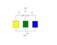
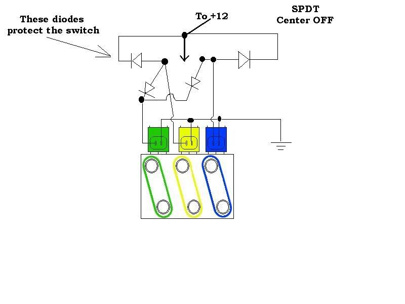
When No Power is applied to the block, the Green Hyd Circuit is "Live" (Off Position on switch)
When I want to use either the Yellow or Blue Hyd Circuit, I need to also energize the green which shuts that port down.
How?...I Realize the diagram is unfinished...
divwiring.gif
 
   / Electrical Circuit Help Needed #3  
You can use 2 diodes to isolate the circuit that must be powered in both positions...

Hopefully I can get this to paste an image. It is not nearly as pretty as yours but hopefully you can tell what I mean.

--Rick
 

Attachments

  • circuit.JPG
    circuit.JPG
    11.6 KB · Views: 220
   / Electrical Circuit Help Needed #4  
I think Kenny D has the right answer.
 
   / Electrical Circuit Help Needed #5  
you, my friend, have drawn a SPDT switch, but described a combination of things that can't happen with your diagram.

if you truly have a SPDT switch, you have 12 volts feeding the center terminal and on the down throw in your diagram, you energize green and yellow. this is not really the "off" position but rather throw "A". on throw "B", or up in your diagram, you energize blue.

here's the part i don't understand:

"When I want to use either the Yellow or Blue Hyd Circuit, I need to also energize the green which shuts that port down."

Why is this? Is there a latching relay in the circuit somewhere or some other reason you have to energize and re-energize green to shut it down? The way it's drawn and with the switch you describe, once the switch is moved from position "A" to "B", anything hooked to "A" is no longer energized.

The answer would determine what you need to do. A complete diagram using regular circuit schematics whould be helpful.

Circuit Schematic Symbols

amp
 
   / Electrical Circuit Help Needed #6  
Not 100% sure, but it would seem to me to add a wire from the green to the blue (+) just like you have the yellow and blue drawn in your diagram. When you activate the switch to activate the blue, the green gets activated also. Same with the yellow and green. Like I said, I'm not 100% sure so I hope someone will verify before you do it.
I was told by a friend to put a diode between the + and - of each switch to extend the life of the switch. Make sure the band is on the + side of the terminal.
 
   / Electrical Circuit Help Needed #7  
Wasn't sure of your explanation of what you were doing. Would these work?
 

Attachments

  • reverse_cct.gif
    reverse_cct.gif
    10.4 KB · Views: 241
  • reverse1.gif
    reverse1.gif
    4.5 KB · Views: 202
   / Electrical Circuit Help Needed #8  
Dave,
From your description, I can see how Schmart's came up with his schematic. But then if that is what you want, you might as well just hardwire +12V to the green since it's always on. I think that's what's confusing us. We're not sure what you want.

1) Are the green, yellow, and blue boxes supposed to represent solenoid valves?

2) Does this SPST switch have a center-off position by chance?

Here's my guess at what you want:

Switch thrown to position A:
Only green is energized.

Switch thrown to position B:
Yellow and Blue are energized as well as Green.

Switch in the center:
Nothing energized.

If that is what you want, the attached schematic would work for you.

If not, please clarify.

You can buy diodes at Radio Shack. Just make sure the forward current rating (usually written I/f (the f is a subscript)) is high enough to carry the amperage drawn by your solenoid valves. I have no idea what that value is, maybe 1 amp? Higher is ok and safer. This one handles 6 amps and should be more than adequate at $2.49 Radio Shack Catalog #: 276-1661.

If you want to install the diodes suggested by 3RRL's post to protect your switch from arcing, use the $0.99 Radio Shack Catalog #: 276-1102 (1N4003), connecting one across each of the solenoids with the banded end NOT on the side connected to ground.

PS: I think where you have -12vDC in your diagram you probably meant 0vDC (unless you have a 24 volt system).
 

Attachments

  • circuit.gif
    circuit.gif
    3.3 KB · Views: 141
   / Electrical Circuit Help Needed #9  
schmart said:
You can use 2 diodes to isolate the circuit that must be powered in both positions...
--Rick


Rick has it right,
This switch is powering solenoid's, right?
If that's the case then I would add two diodes across both sides of the switch to +12 to prevent arcing across the switch contacts when the switch is opened (turned off). It will protect the switch contacts from burning over time.


Larry
 
   / Electrical Circuit Help Needed
  • Thread Starter
#10  
Sorry to confuse you guys...I appreciate the help thus far! Lemme see if I can answer some questions so we're on the same page.

What I'm trying to do is to wire up the 3 bank Hydraulic Diverter from Surplus Center.....Port 1 (Green in my drawing) on that block is prioritized...meaning with no 12v power to it, oil will flow thru it. So when I use either of the other ports (yellow or blue) I would need to energize the green port which shuts flow off to it and diverts it to either the yellow & blue ports.


TedLaRue said:
1) Are the green, yellow, and blue boxes supposed to represent solenoid valves?
Yes
TedLaRue said:
2) Does this SPST switch have a center-off position by chance?
Yes, its a Center off Switch... On-Off-On to be exact


Switch thrown to position A:
Only green is energized. - No, I would need Green & Yellow Energized

Switch thrown to position B:
Yellow and Blue are energized as well as Green. No, I would need Green & Blue Energized

Switch in the center:
Nothing energized. Correct
 
 
Top