Alternator wiring....

   / Alternator wiring.... #1  

StevenPaul

Silver Member
Joined
Sep 9, 2005
Messages
133
Location
Anderson County, SC
Tractor
John Deere 2010 (Kranky), JD 4500
Hello All!

Is there anybody out there that can post/reply in here or send me an email (Im4theSon@aol.com) for a JD 2010 wiring diagram. I've got the service and parts manuals but it doesn't give a wiring diagram for an alternator system. We've removed the voltage regulator and any excess wiring. We've got a negative ground system with an alternator, coil, starter motor, battery, and ignition switch. Currently there is an amp meter gauge installed. We can get it running but the coil gets extremely hot and the ignition switch little coil thing on the back starts to heat up and smoke. We think we have it wired wrong, yet it somehow sometimes works. Obviously I'm not an electrical engineer so any replies, please be as simple as possible. At first it acts like it wants to start up then the battery dies and we have to end up usually jump startin it. It's like something is constantly draining the battery. Any and all help would be greatly appreciated.

thanks!
Steve
Anderson County, SC
 
   / Alternator wiring.... #2  
Very difficult to advise on electrical problems without seeing the system and/or running tests but if you've removed the voltage regulator from the system, you could possibly have upwards of 19 or 20 volts from your altenator and quite a few amps!! If you're not going to use all the original electrical system, you need to install an altenator that has an internal regulator and 1-wire hook-up (internally excited) - they can be had for under $40. The 1 wire is usually a 10-ga. wire to the positive battery post or where the positive cable hooks to your starter. Your charging voltage should run between about 13.4 to 14.8 VDC. Your ignition coil has to be resisted for a point-style system, whether internally or externally. The simplest is the internal and you can hook system voltage right to it from your ignition switch. Point-type coils are supposed to operate at approx. 9 or 10 VDC, except for initial starting, so you have to add a ballast resistor if using an externally resisted coil. Running higher voltage will cause points to burn/pit very quickly and eventually burn-up the coil. Make sure you have good grounds everywhere too. Maybe this helps a little - good luck.
 
   / Alternator wiring....
  • Thread Starter
#3  
I did forget to mention, that we do have a 1 wire alternator. As for the internal/external coil stuff, not sure about that. All I know is that it's a pretty new 12V coil and it does have a wire going to the distributor. I've got 4 hook ups from the ignition switch, BAT, IGN, SOL, & ACC. I'm needing to know where do the all the wires go from the ignition.

thanks again for the help!
Steve
Anderson County
 
   / Alternator wiring.... #4  
Does the coil have an internal resistor ? Or does it use an external resistor ? Basically all coils are 6V , they either use an internal or external resistor to limit current. some systems have the resistor out of the circuit for starting and the coil in circuit for running. Some have coil in the circuit all the time.

I am assuming that this tractor has a gas engine.....

Ben
 
   / Alternator wiring....
  • Thread Starter
#5  
ok, talk about feeling like an idiot, I just went out and looked (in the rain) and it's 12V coil and it says, external resistor required. Sheeeesh, what a man I am! hahaha! reading the directions after installation. Ok, so what do I do after getting the external resistor? And where do I go with all the other wires from the ignition switch?

thanks again!
Steve
 
   / Alternator wiring.... #6  
The resistor will go in series in the positive lead going to the ignitin coil. Prob the IGN term on your switch. I don't really know in your situation where the rest of the wires go, sorry. here are some ideas.

ACC = to lights and such
BAT= to battery
Ign = to coil
I have run the little lead out of some one wire alternators to the IGN leas as well, so that the alt is cut off when the switch is off.

Ben
 
   / Alternator wiring....
  • Thread Starter
#7  
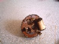
here's my ignition switch, and I'm an idiot twice today, trying to break my record of being one all day I guess, haha! Anyways, the letters on it are I(ignition), B(battery), L(2 prongs = lights?), S(?), & F(?). The other identification I previously posted was for an ignition switch we used in place of the original one for a while. Does this help anybody with being able to tell me where the wires should go?
 

Attachments

  • 749956-M4100012.JPG
    749956-M4100012.JPG
    14.6 KB · Views: 220
   / Alternator wiring.... #8  
L is probably lights.
S might be starter, wires to starter solenoid.
F hmmm could be field for the alternator or maybe fuel shutoff, not sure at all on that one.

Ben
 
   / Alternator wiring....
  • Thread Starter
#10  
thanks y'all, just went out and bought the resistor for the coil, "F" for fuel gauge makes sense, but I don't have one. Now all I have to do figure it all out. If y'all think of anything else, let me know. I'm kinda pieceing this thing together with your help and what I'm finding on the internet.

Steve
 
 
Top