Ford851
Bronze Member
Hello again,
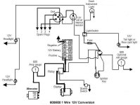
Can anyone explain to me what a Ford 851 electrical layout is suppose to be after it has been converted over for 6 volt to 12 volt? I took my tractor apart to work on the sheet metal. This took about 4 months. Now I'm fitting the metal parts back on the tractor and realized that the wires are not where i left them. My pet cats have had a field day playing with the dangling wires. I know i should have labeled them, but it seamed so simple at the time i took it all apart. Its like I think I know but then again I could make a mistake and burn up the wiring.
Let me try to explain what I think I have:
Starter circuit----From the 3 pole solenoid.
1. Battery 12 +(Red cable) to the large terminal on the solenoid
2. Opposite side of solenoid (large terminal) to starter terminal.
3. Center post on solenoid (white wire) goes to starter button in front of driver's seat.
The charging circuit---
1. From the alternator a 10 or 12 gage wire runs to one side of the ammeter.
2. From the other side of the ammeter a 10 or 12 gauge wire runs to the plus side of the solenoid. Where the heavy red cable is attached that runs to the plus side of the 12 volt battery.
3. A splice has been put in the wire mentioned in number 2 which runs to the ignition switch post. Supplies 12 volts
4. The other side of the ignition switch then runs to a large white resistor. (about 1.5 ohms) Drops volts to 6 volts
5. The other post of the this resistor then goes by a white wire to the coil primary. Open and closed by points
6. Secondary of coil delivers high voltage to distributer center rotor and then out to plugs.
There was also a small two post terminal block bolted to the steering column and I can't remember what its function is.
The schematics i've seen so far in the manuals leave a lot to be desired when it comes to clarity. I'm curious about the ammeter circuitry. And also there is an orange wire in the harness which I have no clue as to what it does.
Any help at this point is greatly appreciated as I would like to get this tractor back in the field.
Thanks in advance,
Ford851
