City Farmer
Platinum Member
- Joined
- Jan 3, 2013
- Messages
- 527
- Location
- Chesterfield, Mi
- Tractor
- Ford 3000, 4400 & 4500TLB Case 830 Case 350 dozer
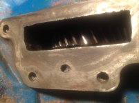
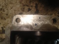
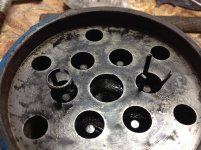
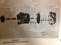
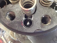
Hopefully someone can help me. I'm rebuilding the hydraulic pump and I have a little confusion. The "Cover & Pin Assembly" diagram shows the inlet ball cage with the 3 prongs facing up, that's the way they were when I pulled the pump apart. The service manuals exploded diagram shows them prong up but someone took the time to write "Turn around" with an arrow pointing to the cage in my manual. On the other half of the pump the cage goes in with the prongs(or feet) going in the pocket first. I'm thinking there was a misprint with the cage prongs facing up. Here's some pictures of what I'm looking at. One of the service manual, one with the prong facing up and down. The last pic is of the mating half with be prongs facing down. I'm thinking that's the way they're supposed to go in.
Attachments
Last edited:
 Sometimes they are a kinda hard to put in the head end (your first pic). Just make sure they are flush with the flat surface around them before reassembly.