Thanks to everyone, you guys are great. Anyhow, I couldn't find the exact article...but did find a similar on a british forum.
Here is what I did.
First, I removed the cover where the optional hydraulic block would be installed.
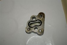
My brother-in-law (a toolmaker) took a bunch of measurements of the inlet and outlet ports and the location of the three previously unused bolt holes. He then manufactured an adapter block out of a chunk of scrap aluminum that was laying around his shop.
The reason that it is so tall is because he staggered the inlet and outlet in order to increase the wall thickness between the two ports. (he looked up the hydraulic pressure for my machine and even took into account the nipple threads...that must be why the original article talked about TIG welding the nipples in place)
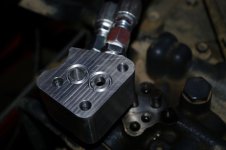
He machined out an O-Ring channel around each port...and if my memory serves me correctly...he left .015" of the rings protruding from the channels. He said this was more than is typically needed, so he squared off the channels instead of the normal rounded ones in order to provide some room for the rings to expand into.
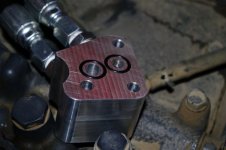
He did not feel positive about the port locations on his adapter plate, so he suggested that I install a couple of dowel pins and verify that everything would line up correctly. (I didn't have the correct size dowels, so I simply cut off some old drill bits)
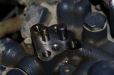
Everything lined up perfectly. So I chased out the bolt hole threads (they had a little bit of rust nodules in them)
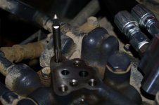
Then I bought some new 8mmX50mm 1.25 thread allen head bolts and installed the adapter plate, tightened up the hose connections, and checked for leaks.
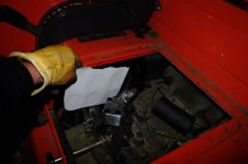
All that I wanted to do at this point was to create a hydraulic "loop" that I could hook into. I know that I cannot dead-head this loop...it is not as convienient as factory rear remotes...But here is a picture of the hoses at the rear of the tractor, hooked together with quick connectors.
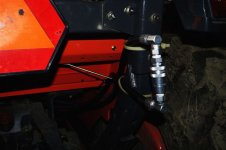
And finally, a picture of the adapter plate installed. (I know that the picture is not clear enough for you to read...but my brother-in-law even etched the O-ring part number and dimensions into the adapter plate.)
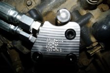
Now I need to put together the plumbing for a control valve and "dump" cylinder for my cement mixer.
Oh...for those of you wondering.....the Total price for the adapter plate....One case of beer.
Here is what I did.
First, I removed the cover where the optional hydraulic block would be installed.

My brother-in-law (a toolmaker) took a bunch of measurements of the inlet and outlet ports and the location of the three previously unused bolt holes. He then manufactured an adapter block out of a chunk of scrap aluminum that was laying around his shop.
The reason that it is so tall is because he staggered the inlet and outlet in order to increase the wall thickness between the two ports. (he looked up the hydraulic pressure for my machine and even took into account the nipple threads...that must be why the original article talked about TIG welding the nipples in place)

He machined out an O-Ring channel around each port...and if my memory serves me correctly...he left .015" of the rings protruding from the channels. He said this was more than is typically needed, so he squared off the channels instead of the normal rounded ones in order to provide some room for the rings to expand into.

He did not feel positive about the port locations on his adapter plate, so he suggested that I install a couple of dowel pins and verify that everything would line up correctly. (I didn't have the correct size dowels, so I simply cut off some old drill bits)

Everything lined up perfectly. So I chased out the bolt hole threads (they had a little bit of rust nodules in them)

Then I bought some new 8mmX50mm 1.25 thread allen head bolts and installed the adapter plate, tightened up the hose connections, and checked for leaks.

All that I wanted to do at this point was to create a hydraulic "loop" that I could hook into. I know that I cannot dead-head this loop...it is not as convienient as factory rear remotes...But here is a picture of the hoses at the rear of the tractor, hooked together with quick connectors.

And finally, a picture of the adapter plate installed. (I know that the picture is not clear enough for you to read...but my brother-in-law even etched the O-ring part number and dimensions into the adapter plate.)

Now I need to put together the plumbing for a control valve and "dump" cylinder for my cement mixer.
Oh...for those of you wondering.....the Total price for the adapter plate....One case of beer.

