grapple hydraulic setup 1026r

   / grapple hydraulic setup 1026r #1  

swick1

Platinum Member
Joined
Jul 11, 2007
Messages
871
Location
WV
Tractor
John Deere 1026R
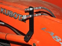
I just got my bosch style diverter valve from surplus center and I'm getting ready to build a mount for it and hook up my hydraulic hoses this weekend or early next week. I'm building the grapple from a sheet of steel diamond plate I got for $60 at the scrap yard. Total cost for the project should be around $500. I'm going to take a few days to finalize the design and it could take a week to get my sheet on the laser cutter or plasma table.

I'll be asking questions and posting pictures as I go. This is my first hydraulic project so I'll go ahead and ask about hose connections first.

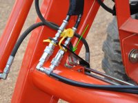
What do I use to seal the threads and how tight should I torque the hoses? (3/8 hose)

Is there anything wrong with using 90 degree fittings on my diverter valve? I think the flow is low enough I can get away with it.
 
   / grapple hydraulic setup 1026r #2  
You only need Teflon paste on the NPT fittings.

Use either 90 degree or 45 degree. No problem.
 
   / grapple hydraulic setup 1026r
  • Thread Starter
#3  
Thanks JJ

Here are the parts I have so far...

1. electrical quick disconnect for removing FEL easily. I will locate this by the hydraulic connectors under the floorboard.
[ame=http://www.amazon.com/ACCEL-74812-Weatherproof-Electrical-Connector/dp/B001HQEUKC/ref=sr_1_3?ie=UTF8&qid=1338477575&sr=8-3]Amazon.com: ACCEL DFI 74812 Weatherproof Electrical 2 Pin Connector: Automotive[/ame]

2. diverter valve and connector
Surplus Center - 12 VDC 13.2 GPM SAE 8 DOUBLE SELECTOR VALVE
Surplus Center - HIRSCHMANN CONNECTOR

3. quick disconnects for grapple
Surplus Center - 3/8" NPT QUICK COUPLER F/F S40-3

4. grapple cylinder (2" bore by 6" stroke)
Surplus Center - 2x6x1.125 DA HYD CYL LION 20LH06-112 3000 PSI

I used a tie rod cylinder because that's the same thing the toro dingo grapple uses which i'm copying my design from.

Here's the dingo grapple I took measurements from at the John Deere dealership: grapple pictures by backhoeworks - Photobucket

I have a lot of 25 joystick handles from ebay coming in. I'll part them out once I find out which one I want to use :)

I'm going to fabricate some brackets and get everything mounted then I think i'll haul the tractor to our local hydraulics shop to get all the fittings and hoses I need. I'm planning on zip tying my hoses to the hard lines that run down the loader arm and either buying or building a bracket to hold my quick disconnects. Any suggestions on how to hold the quick disconnects?
 
   / grapple hydraulic setup 1026r #5  
I would use bulkhead fittings to mount the quick couplers. Get the same type of threads as your couplers and hoses. You will need to make a bracket for the bulkhead fittings.
 
   / grapple hydraulic setup 1026r #6  
with a 3 amp draw probably don't need the relay and could just wire direct from switch to valve. I include two pics I saved from an old post that shows how one guy mounted his quick disconnects. The first is a good pic of the bracket, second is of the bracket mounted. Send some pics on how you mount the valve. I have the same valve and am trying to find a way of mounting it to the FEL on my Kubota L3400HST. I plan to tap into the lines were the rubber hose connects to the solid line. Can't figure a way to mount it without welding or drilling into FEL arms. Like to see what you come up with.
 

Attachments

  • 12-bulkhead-plate.JPG
    12-bulkhead-plate.JPG
    69.9 KB · Views: 1,590
  • 17-plate-angle.JPG
    17-plate-angle.JPG
    94.3 KB · Views: 1,402
   / grapple hydraulic setup 1026r
  • Thread Starter
#8  
Thanks for the bulkhead fitting tip. I've done it before with lab tubing! Never thought about it for hydraulics!
 
   / grapple hydraulic setup 1026r
  • Thread Starter
#9  
Murphy, I can't see why it won't work. What am I missing?
 
   / grapple hydraulic setup 1026r #10  
Here's my electrical diagram for the selector valve. I made this for my dad to do this weekend:

http://i1196.photobucket.com/albums/aa415/backhoeworks/grapple/elec.jpg?t=1338564491

NOT RIGHT!

12 volt positive should NOT go to the valve from the battery.
The valve needs a ground.
12 volt positive for the valve should come from the switched (normally open) terminal of the relay
The relay needs a 12 volt supply to the common terminal of the relay. It should be protected, fuse or circuit breaker. It can be direct from the battery or from a source only "hot" with the key ON. As long as circuit choosen will support the amp draw of the valve.

The relay has a coil. When current energises the coil the relay switches the power to the valve. You need to get 12 volts across the coil of the relay. There are several ways to do that. If you want it to only work with the key ON you need to find a 12 volt supply that is only "hot" with the key on. You can then send this 12 volts to your joystick switch, from the joystick switch to the relay coil. Then gound the other side of the coil.
OR you can send this 12 volt supply to the relay coil, then from the other side of the relay coil go to the joystick switch, then from the other side of the joystick switch go to ground. This way may take less wire.
 
 
Top