Bandara, as you can tell by JJ's post count, he has helped hundreds of us on hydraulic problems, including me - but English is my ONLY language, and I still had to find out what some of the "new language" meant. I'll try to help with that, and maybe some insight on your hookup, since I've been working on a similar one.
First, some abbreviations
QD = Quick Disconnect, see here
ISO 5675 Agricultural Hydraulic Quick Couplers
PB = Power Beyond - this is a second output port on a hydraulic valve assembly. The "output", or "tank", port on most valves is NOT capable of handling high pressures that the hydraulic pump puts out, because in normal operation this output port only returns the hydraulic fluid back to the tank, where the pump then re-pressurizes it and sends it out again.
A lot of hydraulic valves have a PB port, but not all - some offer PB as an option, often it is just an adapter that screws into a hole in the valve that would otherwise be plugged. Here's one with PB
Surplus Center - 2 SPOOL SV VALVE OPEN CENTER W/POWER BEYOND
If you click on the "enlarge" button on that page, you will notice that the right side of the picture shows two large "bolt heads" - these are actually plugs for the two output ports. The one closest to the center of the valve is the PB port. The picture does not show the adapter plug that goes into this port, but it comes with the valve when you order the PB version. This adapter plug is the ONLY difference (at least in this exact valve) between PB and non-PB versions. Its function is to allow full pressure output of hydraulic fluid to power a down-stream device (in your case this would be your lift (3 point hitch)
The PB option is necessary for your application, because the NORMAL output of these (and most) valves can NOT withstand full hydraulic pressure or it will cause the inner seals of the valve to FAIL.
You NEED this full pressure passed along to your lift, or it won't work.
There are cheaper valves available that are a one piece casting, some offer "loader" functions - these would have one spool with spring loaded center position, plus one spool with an added "float" position.
Like this
Surplus Center - 2 SPOOL 8 GPM PRINCE MB21GB5C1 DA VALVE W/FLOAT
You would also need this
Surplus Center - P-BEYOND & CLOSED CENTER PLUG 8 GPM MB VALVES
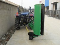
I would recommend this type valve because I see your flail has the same rear roller that my flail mower has - its purpose is to control mowing height. If you connect the float half of the valve to the TILT function of your flail, placing that valve in float position would allow the ROLLER to control the angle of the mower.
Your lift valve, when lowered all the way, should allow the whole mower to rest on this rear roller - the "float" position on the half of the valve used for "tilt" would allow the roller to follow the shape of the ground for a more even cutting height.
It isn't clear from the pic, but looks like the second hydraulic cylinder controls extending the mower more or less to the side of the tractor. This cylinder would only need the 3-position (non-float) half of a loader valve.
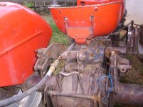
I am not sure which country your MF 135 was built in, so you will probably have to trace your hydraulic system from the pump til you find the 3-point hitch lift valve - on my tractor, this valve is under the seat. There is a good chance your system is metric, since it is possible your tractor was made in Europe somewhere - once you find the connection to your lift valve, you will need to do one of two things -
1. If you are lucky, the connection to your lift valve will be of a type and size that is available locally. If so, you may be able to get fittings and hoses to re-route this line to the INPUT of your new valve - if not, then
2. You may need to cut your rigid hydraulic tubing and use some compression-type fittings to adapt to the type fittings your new valve needs. If this is necessary, you will need to know the EXACT OD (stands for Outside Diameter) of your existing hydraulic tubing - on my Allis Chalmers, this is 12mm.
Example of these fittings
Compression Fittings for Metric Hydraulic Tubing
For more specific help, I would need to know what you find out about your specific tractor's connection types and sizes - this page may help with that
http://www.discounthydraulichose.com/v/vspfiles/downloadables/thread_guide.pdf
As to your concern about having the lift UP or DOWN - I don't think this will matter. Unless the MF 135 is different than most tractors, this is how it works -
The system is likely to be "open center" - this means that the pump moves oil through the system and back to the tank at ALL times if the motor is running. Unless you move the lift control, there is very little pressure ANYWHERE in the system (except inside the actual lift cylinder, if the implement is not resting on the ground) -
When you raise the implement, the lift valve TEMPORARILY sends oil to the lift cylinder, and ONLY until the position of the lift CONTROL matches the position of the lift CYLINDER - then the lift valve automatically goes back to NEUTRAL position, and once again the oil is only being pumped through the OPEN CENTER of the lift valve and back to tank. No work being done = only enough pressure to get the oil to circulate.
It should not matter what position your lift is in for your NEW valves to work - only that you can use only ONE hydraulic function at a time and still get full hydraulic flow to that function. This means that you should be able to use the new valves REGARDLESS of your lift being up or down.
Depending on what year your MF135 was made, it may not have flat enough fenders to mount a valve on - if so, you might need to give some thought to a way to mount the new valve so it is easy to reach and operate - if you can post a picture of your tractor it would help with this part of the project.
It took a while to write all this, so JJ may have already answered some of your questions - I'm in the process of finding all this out for my own use, so thought I'd share some of the things I had to learn... Steve