adding top and tilt

   / adding top and tilt #1  

runningbird

Gold Member
Joined
Oct 12, 2005
Messages
297
Location
Gisela, AZ
Tractor
yanmar 1110d ,fx28d
I'm looking for a bit of help. I have searched and found quite a bit of info but want to make sure I get this right.

I would like to add a top and tilt to my Yanmar FX28. I have a loader on it and will post pictures of my existing set up.


this is a picture of my loader valve, I'm thinking a power beyond could go in the top port which is not being used?

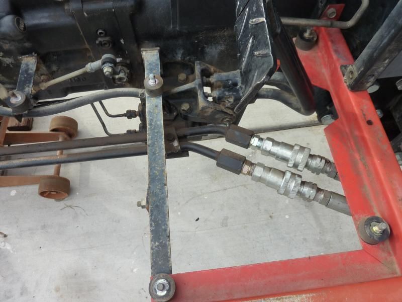
The hydraulic lines to the loader valve come from under the right foot rest. there is an on/off lever under the seat that controls the flow to those lines. I'll add some pictures here. This where those two lines come off.


this is where they end up under the right foot and connect to the loader lines.
 
   / adding top and tilt
  • Thread Starter
#2  
I will add a couple pictures and questions at this point. I'm wondering if this plug might be a spot for a return line?


on the left side there are these to plugs or maybe not plugs, They are not marked like the lines on the right side. Is there a chance they could be pressure lines?


This is a picture from the front. this is the line from the pump entering the system. along with the 3pt drop speed knob.
 
   / adding top and tilt
  • Thread Starter
#3  
I hope the picture will help someone help me. a question I have is, Is the best spot to get flow, out of the loader valve? Or would it be better if possible to get it somewhere else. What kind of valve or controller would work best?

Thanks for any help! I am at work and will check back when I have a chance.
 
   / adding top and tilt #4  
How is your flow path? Point to point.

Is it from the pump to the loader then to the 3pt?

If the loader valve is feeding the 3pt now, then you can assume that the loader valve has a PB port.

Do you have six or seven hoses on the loader valve?

If you have PB coming to the 3pt now, then you can interrupt the flow at the 3pt for the remote valves for the T-N-T.
 
   / adding top and tilt
  • Thread Starter
#5  
Flow path, I'm not sure, on my last picture that is the line from the hyd pump. On my second picture you can see that same line has well has the out and in lines that go to the loader valve. If I had to make a guess it would be pump-loader-3pt. if I did not have a loader the lever would be off, thus eliminating the two ports on the side that go under the rt foot and up to the loader.

There are six hoses on the loader valve. The top of the valve has a port which is not being used and I thought that would be a spot for the PB.

I'm sorry if I have not explained things well. and thanks for the help.
 
Last edited:
   / adding top and tilt #6  
Find the port on the loader that feeds the 3pt and see if that port has a PB stamped by it.

The hyd may exit a hyd block and return to the hyd block and then to the 3pt.

Back track the hyd line going to the 3pt and see where it goes.

Who is the manufacturer of your loader valve?
 
   / adding top and tilt
  • Thread Starter
#7  
The hyd may exit a hyd block and return to the hyd block and then to the 3pt.

This is how I think it is. I will check the loader valve and port when I get home.
these are the exit and return lines at the block. but I will check the loader when I'm home.


Thanks so much for the help.
 
   / adding top and tilt
  • Thread Starter
#8  
so I checked the loader valve last night. the line on the bottom entering the valve is the in for the pressure. here is a picture of that point.


has you can see it is marked P i'm figuring that means the pressure connection. on the hydraulic block the same line is marked O for out I think.
 
   / adding top and tilt
  • Thread Starter
#9  
after that I have ports that go to the loader cylinders. and at the top of the valve is the out port which goes back to the hydraulic block which is marked I for in I guess.


on top of the valve is another port which is not being used and it does not have a marking on it.

 
   / adding top and tilt #10  
Logically speaking, a loader valve will have 7 ports.

In port = supply in

Tank port = cyl flow out

2 work ports for in and out for each cyl. total of 4

PB port with adapter = flow for the next valve.

It looks like someone got lazy and and connected the tank port back to the hyd block.

Normally the PB connection will feed the hyd block or the 3pt.

Most tank ports go to a tank line and is low pressure.

Most tank ports have a limited psi rating of about 500 psi.

Did you find the manufacturer of the valve?

You could remove the large hex plug and show a picture of the inside.

What you are looking for is a port that will accept something like this adapter to make the port a PB port.
 

Attachments

  • PB adapter.jpg
    PB adapter.jpg
    70.5 KB · Views: 222
Last edited:

Tractor & Equipment Auctions

Ford Super Duty 8ft. Truck Bed (A49346)
Ford Super Duty...
2014 Freightliner M2 106 Ambulance (A50323)
2014 Freightliner...
2016 HITACHI ZAXIS 210LC-6N EXCAVATOR (A51242)
2016 HITACHI ZAXIS...
2014 INTERNATIONAL PROSTAR (A50854)
2014 INTERNATIONAL...
2015 KENWORTH T800 MID-ROOF SLEEPER (INOPERABLE) (A50854)
2015 KENWORTH T800...
PALLET OF PIPE CLAMPS (A50854)
PALLET OF PIPE...
 
Top