Hydraulic diagram ISEKI TF 330 or tf 325 or MF 1230, 1235

   / Hydraulic diagram ISEKI TF 330 or tf 325 or MF 1230, 1235 #1  

Tonicci

New member
Joined
Nov 24, 2013
Messages
23
Location
KVL, Finland
Tractor
Gone,ISEKI TF 330 4wd Hydrostatic, in use Valmet h480 1991,in repair antonio carraro supertrac8400 htm 2005
I have problem.

3 point hitch lift as cycles 5 sec/5 cm and same time idle drops. Sounds like it produce pressure and then something(relief valve maybe) opens and arms move a bit. then again same.

also steering is sticky. There is enough hydraylic oil.

Aux hydraulic at rear not working. i did try both.

Does anyone own hydraulic diagram, so I can start troubleshooting... ???
I have ask finnish importer, but no help..
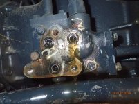
Tractor is equipped with extra block next to original valve block. Dont know, if hoses are correct front loader was removed when i did buy it.

Iseki tf 330 and mf 1235 is same tractor
almost same is
iseki tf 325 and mf 1230

skywalker.t (a..t ) gmail . com
 
   / Hydraulic diagram ISEKI TF 330 or tf 325 or MF 1230, 1235
  • Thread Starter
#2  
   / Hydraulic diagram ISEKI TF 330 or tf 325 or MF 1230, 1235
  • Thread Starter
#3  
IMG_1616.jpg

Here is extra block removed . From right pipe oil from pump, lowest hole nr 1 oil was coming out, when I did start tractor. Above hole nr 3 is relief valve and above 2 pipe is going to 3 point hitch. . I think I have to take hose from one to loader block and back, but where I should connect return? 2 I assume, but then I am in start point. 3 point not working prroperly

Do i need t-piece between 2 and 3 or just plug nr 3 ? wondering, if relief valve i then disconnected? IMG_1618.jpg
I don't have original cover plate to check if 2 and 3 is connected together.


lower photo extra block with 3 connections.


When I did get tractor nr 1 was plugged and 2 and 3 connected with loop. Gaskets was broken when I did start (of course if there was plug on number 1. (Coming from pump).
I did change loop between 1 and 2 and plug to nr 3 --> gaskets ok, but 3 point linkage lifts with cycles not working properly.

I have some t-pieces and plugs +gauge. I can measure pressures, but any ideas what comes to connections between 2 and 3 ? However I think pressure is ok as it broke the gaskets.


Anyone can help?
 

Attachments

  • IMG_1616.jpg
    IMG_1616.jpg
    269.9 KB · Views: 1,321
Last edited:
   / Hydraulic diagram ISEKI TF 330 or tf 325 or MF 1230, 1235 #4  
Were hoses connected to this block?

Do the holes have threads?

On Kubotas, the pressure comes from the hyd block , goes to loader and the loader PB comes back to the block, then another port from block feeds the 3pt. Loader tank line comes back to block also.

All tank lines go to tank, and can be teed.

Is there not an adapter cover for the hyd block to facilitate loader installation? .
 
   / Hydraulic diagram ISEKI TF 330 or tf 325 or MF 1230, 1235
  • Thread Starter
#5  
When I did buy tractor nr 1 plugged, 2+3 looped. (i think someone has remove loader after tractor gearbox was broken and only connect hoses somewhere to keep oils in.
gaskets broken immediately after start).

I switch plug to nr 3 and loop between 1 and 2 no gasket damages anymore.


Last nigt 15cm snow.. and snowing.. Why I don't do things early...:pullinghair:

There is threads connections are same numbers with or without extra block. in extra bloc 3 not marked are attached screw holes. NR3 is drilled from the side. Extra block is attached.

I did make some markings to first post photo.
now i did make test.
from connection nr.1 I did pull hose to loader block inlet and to that line i did attach t-piece + pressure gauge.
Back from loader block hose to nr 2
3 temporary plug.

My theory. When I turn loarer lever , I should get pressure as flow through loader block stops and gauge is between pump and loader block...

BUT
very strange actions. I did start tractor suddenly lift pressure +100 bar and drop back. Then I did turn rear auxiliary hydraulic and pressure "visits". then away. I did open from bottom air screw nr 39(as instructed to some seconds and it push maybe one liter oil out and then nothing). for me it should come out all the time.


while loosening loader outlet hose it seeks to work like it should. oil comes out, but when I use loader levers, it stop. so from block to loader I assume all hoses ok.


strange notice was, that return Hose (short elbow NR7 in drawing) from rear end tu pump inlet was "sucked in". Don't know correct word, but it seems that there is under pressure, but no oil enough.

seems that some problem between block and pump. on that part is been auxliary hydraulic, 3 point hitch and slow return screw. I will remove seat and plate tomorrow to see it better. now its getting dark here.. (afternoon half past 3 )


for me it seems that in original block flow is coming out from number one and if there is too much load, relief valve opens and let oil come out from nr 3. for me it means that nr2 and 3 must be connected together. otherwise relief valve don't work. How ever on drawing there is also "inside" of the original block O-ring (nr 40)
can there be whole straight to rear end. there was oil coming out all the time from nr. 3 when it was disconnected, so it could go straight to tank. in that case 3 can be plugged and relief valve still works.
block.JPG

And maybe tomorrow.... NR1 filter should be checked....
 
Last edited:
   / Hydraulic diagram ISEKI TF 330 or tf 325 or MF 1230, 1235
  • Thread Starter
#6  
This problem solved.

rubber hose shows some indication of flow problem. from papers I noticed filter nr 1...
Well... quite dirty... Someone has made good maintenance. No chance to get new filter easily, so old one is now washed with diesel + pressurized air. aAso inside the rear end cleaned. All seems to work and pressure +150 bar

IMG_1622.jpg
 
 
Top