Please help identify inflow and outflow ports for remote install

   / Please help identify inflow and outflow ports for remote install #1  

budepps3760

Silver Member
Joined
Mar 4, 2014
Messages
207
Location
Montgomery, Al
Tractor
Mahindra 2810
I have a Mahindra 2810 and I am working on installing top and tilt on it. There are currently no hydraulics except for the 3PH. I removed my seat and identified what I believe for certain 1 of the ports and possibly the second.

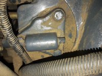
The first picture shows what I believe to certaintly​ be a port. It is horizontal in orientation and has a small threaded plug installed.
1491495269759.jpg


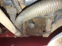
The second picture shows what I believe to be a second port. Whereas the first port was horizontal and fairly small, the second picture shows this potential port to be larger in diameter and vertical in orientation. As I examined this second tube/port it definitely has a threaded cap on it.

1491495333297.jpg


These are the only 2 possible ports that I could find in this area. Based on the different diameters of the 2 ports, which would be the outflow from the tractor to the control levers, and which would be the return flow from the control levers back to the hydraulic fluid reservoir on the tractor?

I am working with fitrighthydraulics, a company that comes highly recommended by the folks on this forum. I appreciate any help that you could provide.
 
   / Please help identify inflow and outflow ports for remote install #2  
Typically you connect things "in line" using power beyond ports. Typical flow for most units is a line from the pump to the loader valve, another line from the loader valve to the valve(s) controlling the hydraulic ports on the rear, and another line from the valve for the rear ports to the 3 point lift, at which point it dumps back to the tank.

If all you have is a 3 point lift, I would think there would just be a line from the pump to the lift. Remove that line, connect it to your new valve(s)s for the rear ports, and connect a new line from the PB on the new valve(s) back to the 3 point. The key is ensuring the new valve(s) are suitable to the tractor, open center, GPM, etc...

Hope this helps, or at least bumps the thread and gets someone more knowledgeable on your model involved.
 
   / Please help identify inflow and outflow ports for remote install
  • Thread Starter
#3  
The is actually no associated with my 3PH. The hydraulic fluid is coming from the fluid reservoir that serves the PTO and the lift arms. The first picture shown actually sits on top of the rear axle.

I understand about the route that you explained. My confusion is to how I return the hydraulic fluid back into the reservoir since I only have 1 port pictured in the first picture. That's why I am wondering if the vertical pipe pictured in picture would be where the fluid is returned.
 
   / Please help identify inflow and outflow ports for remote install #4  
The is actually no associated with my 3PH.

You lost me there.

The hydraulic fluid is coming from the fluid reservoir that serves the PTO and the lift arms. The first picture shown actually sits on top of the rear axle.

The fluid in the reservoir should go to the pump and the pump should feed the lift. Have you identified where the pump is? It should just be a matter of plumbing your valve(s) in that line from the pump to the lift.
 
   / Please help identify inflow and outflow ports for remote install
  • Thread Starter
#5  
The only pump on my tractor is a pump for the power assisted steering. There is the hydraulic fluid reservoir which actually serves as the transmission fluid and operates the lift arms. There is no external hydraulic fluid lines associated with the PTO or lift arms.

Sitting directly under the seat was the area represented by picture 1. The picture contains, what I believe to be, a diverter plate with the threaded nut sticking out the side. I believe that would be the place where I would attach a hose to enter into the loader valve. If indeed that is a diverter plate to attach my line to the loader valve my concern then becomes where do I return the hydraulic fluid back into the reservoir.
 
   / Please help identify inflow and outflow ports for remote install #6  
That makes me wonder if you wouldn't need to add a pump to get external hydraulics then. I wonder if a pump is part of the ML108 loader kit for that tractor?
 
   / Please help identify inflow and outflow ports for remote install #7  
The 3 pt hitch requires a hyd pump to raise up & I'll bet your tractor has a pump for that purpose.. I suggest you acquire a technical manual for your tractor & study the manual before attempting to add any hyd valves. PLEASE Before you attempt to open any hyd fittings or lines please wash your tractor to remove the dirt.
 
   / Please help identify inflow and outflow ports for remote install #8  
I have a Mahindra 2810 and I am working on installing top and tilt on it. There are currently no hydraulics except for the 3PH. I removed my seat and identified what I believe for certain 1 of the ports and possibly the second.
The first picture shows what I believe to certaintly​ be a port. It is horizontal in orientation and has a small threaded plug installed.
View attachment 504786
I am pretty certain that is your port. If you CLEAN the dirt off, then remove the three bolts, there are probbaly three holes under it with oring seals around them. Two are high pressure in and out (one is at each end of that "tube" on the plate and the return to tank is under the slightly rounded edge on the lower side. The plug in there is for a pressure tester
Mahindra probbaly sells a plate to do that. If it is like one for the Kubota L3830, it should be around $30.

Aaron Z
 
   / Please help identify inflow and outflow ports for remote install
  • Thread Starter
#9  
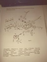
I do have a technical manual and reviewed the drawings. This first picture from the manual shows the hydraulic pump in place on top of the transmission. The 2 lift arms are shown on the upper back location of the picture as well as the various components on the hydraulic pump.


1491571130690.jpg


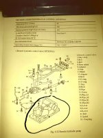
The next picture from the manual shows the addition of a hydraulic remote system added to the pump. The various components of the remote system and a general location for the system. In this second picture I have circled the existing hydraulic pump currently installed on the tractor.


1491571237632.jpg


In looking at this second picture of the manual I am still at a loss to identify a flow out port and a flow in port. Maybe I am just not seeing it. I do see what appears to be one port for flow but not a second.
 
   / Please help identify inflow and outflow ports for remote install
  • Thread Starter
#10  
Thanks Aaron
 
 
Top