huffman102833
New member
I wrapped up this install last night and want to provide a summary incase anyone else finds it useful. The original thread can be found here: http://www.tractorbynet.com/forums/hydraulics/389286-new-holland-boomer-41-rear.html
PART NUMBER: MT20140706
Total install time was between 5-6 hours, but a lot of time was wasted figuring out the instructions were incorrect.
Tools needed:
22mm wrench\sockets
27mm wrench\sockets
14mm socket
12mm socket
10mm socket
phillips & flathead
Removal\prep
-Right rear tire
-Seat (6x 12mm bolts)
-Access panels (3 12mm bolts on right hand side of seat with plastic caps)
-Right-hand paneling (Phillips screws and a few 10mm bolts. Plastic handle on 3pt slips off with a little muscle)
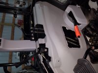
-Remove hydraulic line from the bottom of loader valve body.
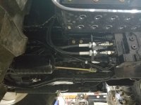
New Valve Assembly (Kit instuctions are mostly clear but the rear lines are out of order. I'll explain more below.)
-Riser fittings on the ports closest to the valve control arms.
-Install clevis in control arm.
Bolt new valve to tractor
-Metal bracket is included in kit but this was already installed on my tractor from the factory.
-Valve body will secure to bracket with 3 bolts.
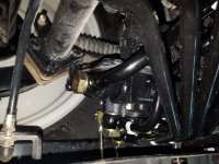
-See drawing below for line connection.
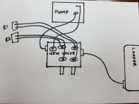
Since the PNs in the instruction manual are incorrect for the remote lines to the rear of the tractor, it may be eaiser to use the picture below to lay them out.
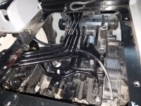
Rear Connection
-Bracket mounts with bolts facing the front of the tractor.
-Secure backing plate to bracket. This will secure the metal lines between the backing plate and bracket.
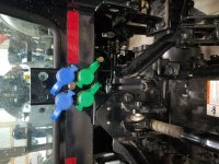
-Thread quick connect couplers on metal lines using liquid thread sealant. The lines are tapered and will only thread on about 1/2 way.
PART NUMBER: MT20140706
Total install time was between 5-6 hours, but a lot of time was wasted figuring out the instructions were incorrect.
Tools needed:
22mm wrench\sockets
27mm wrench\sockets
14mm socket
12mm socket
10mm socket
phillips & flathead
Removal\prep
-Right rear tire
-Seat (6x 12mm bolts)
-Access panels (3 12mm bolts on right hand side of seat with plastic caps)
-Right-hand paneling (Phillips screws and a few 10mm bolts. Plastic handle on 3pt slips off with a little muscle)

-Remove hydraulic line from the bottom of loader valve body.

New Valve Assembly (Kit instuctions are mostly clear but the rear lines are out of order. I'll explain more below.)
-Riser fittings on the ports closest to the valve control arms.
-Install clevis in control arm.
Bolt new valve to tractor
-Metal bracket is included in kit but this was already installed on my tractor from the factory.
-Valve body will secure to bracket with 3 bolts.

-See drawing below for line connection.

Since the PNs in the instruction manual are incorrect for the remote lines to the rear of the tractor, it may be eaiser to use the picture below to lay them out.

Rear Connection
-Bracket mounts with bolts facing the front of the tractor.
-Secure backing plate to bracket. This will secure the metal lines between the backing plate and bracket.
-Thread quick connect couplers on metal lines using liquid thread sealant. The lines are tapered and will only thread on about 1/2 way.


