Adding Hydraulic Side Links

   / Adding Hydraulic Side Links #1  

3RRL

Super Member
Joined
Oct 20, 2005
Messages
6,931
Location
Foothills of the Giant Sequoia's, California
Tractor
55HP 4WD KAMA 554 and 4 x 4 Jinma 284
I finally got enough time to start a thread and upload some pictures of my latest project, adding hydraulic side links. I got quite a lesson about hydraulics in my last project so I thought to start this one now.

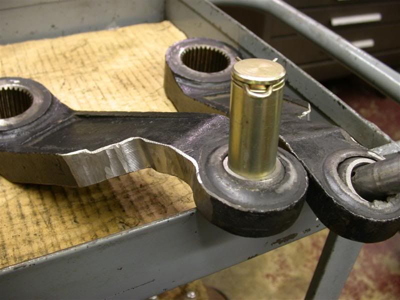
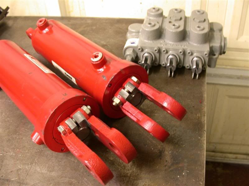
Couple of things I wanted to accomplish were to have beefy hydraulic cylinders to take the place of the cheesy turnbuckles and also to mount double pilot operated check valves on them to prevent any leak down. This is important to me because I use my side links to "cinch" up the backhoe sub frame assembly and it needs to be that way. One other thing was to standardize the hitch pins to Ø1" on both the tractor upper lift arms and lower drag links.

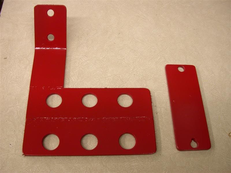
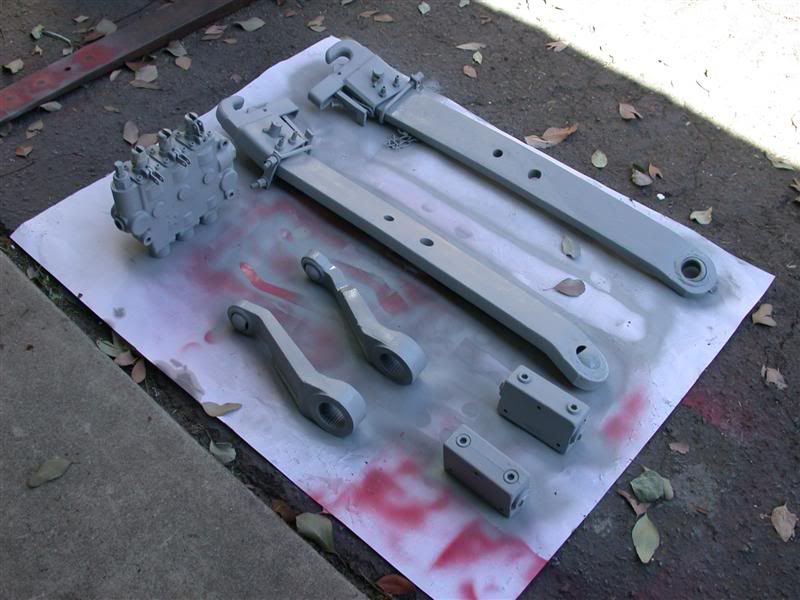
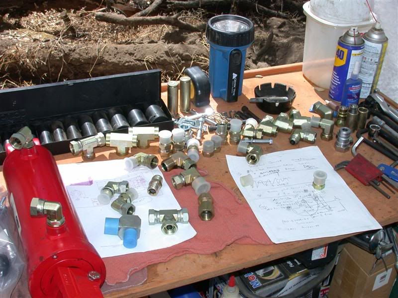
This photo is some, not all of the components for the project. My hoses and the rest of the adapters are still on order.

 
   / Adding Hydraulic Side Links
  • Thread Starter
#2  
I measured the Kama to be certain I'd have enough clearance to get big Chief cylinders and those giant check valves at Surplus Center. I can't wait to try them out. The cylinders are Ø3-1/2" with a Ø1-3/4" shaft and 8" stroke. That should be plenty heavy duty enough to keep from bending, unlike the Ø1' turnbuckle shafts. I measured the travel of the existing turnbuckles and it was 7-1/2" so I'll have to modify the Chief cylinders a little to alter the stroke. I wanted 2 cylinders because I have a dirt road that requires a lot of maintenance and I'm constantly adjusting those side links for crowning the road or cutting gutters, etc. I also use the box blade quite a bit in reverse as a bulldozer blade so this way I'll have a 4 way blade almost like their 6 way blades. Using the box blade in this manner requires heavy duty drag links, stabilizers and side links, or something will bend.

I'm going to attempt to hard-plumb the DPOCV to the cylinders myself. Then also add a Prince 3 spool valve with power beyond. I'm planning to use the new valve to operate the side links and the hydraulic and top link cylinder. Then I'll use the existing rear remote valve to operate the hydraulic box blade with one spare set remotes....maybe...I'm not 100% certain yet.

Anyway, the first thing I ran into was that the new cylinders have a 1-1/8" width between the clevis and my upper lift arms have swivel balls that are 1-3/8 thick. So I had to grind them down to give me some clearance. I did that on the surface grinder in my garage shop.


Heres a picture that shows the difference between the two. Now they fit in between the new cylinder clevis.

 
   / Adding Hydraulic Side Links
  • Thread Starter
#4  
Hahaha...
Next I had to bore open the swivel ball from Ø7/8 to Ø1" and also do the same on the drag links to accept the larger pins. Now all the pins and holes are the same and I can switch them around instead of having all kinds of different sizes to mess with. You know when doing a project like this it's the "little" adjustments you have to make that really adds to the project. It rarely happens that everything you are wanting to do fits perfectly...sometimes not at all.


   / Adding Hydraulic Side Links
  • Thread Starter
#5  
I finally got the bores to be just right...
You can see the good one on the left vs the sloppy one on the right. I also had to mill some more clearance onto the upper lift bars to allow enough pivot room for the larger hydraulic cylinders.


Then I had to make a couple of brackets to accept the additional rear remotes and also for the new valve. So I welded some pieces I had lying around and drilled a bunch of holes in them. I made the rear remote bracket so I can bolt it onto the rear fender. This will put it more out of the way of the PTO and lift links making it safer and WAY more accessible.

 
   / Adding Hydraulic Side Links
  • Thread Starter
#6  
When I pinned the new cylinders onto the top lift arms they now worked great. But the the clevis on the bottom links needed to be cleared more to allow pivoting for the drag link (lower lift arm). So back to the milling machine and started to whack away the interfering portions. I ended up with over an inch of usable thread engagement so I thought that was plenty good. I looked it up to be sure and found that a 1-1/4-12 UNF thread holds 15,000 pounds at 1-7/8" engagement, so the 1'' should give me just about half that per thread....giving the 15,000 between the 2 of them. My tractor will never pick up anything over 3,500 lbs on the 3pt....


OK, so now the clevis is finished machined but when I screwed it back onto the piston , the threaded rod was sticking out about 3/4 inch...that won't work! I filed the threads and determined they were "soft" and I could probably cut them off.

So into the saw to cut off the excess.

 
   / Adding Hydraulic Side Links
  • Thread Starter
#7  
Finally I screwed the clevis's back onto the cylinders and the are ready to paint and install. You can also see the Prince 3 spool valve I'm using.


After that, it's outside the garage for a couple of coats of the primer paint. Then I'll put the final coats on and take everything up to the property to mount to the tractor.


Hopefully the rest of my couplers and the hydraulic hoses will arrive via UPS next week. I'm planning on spending Labor Day on the property with all my kids and grandkids. We will all be camping there. With that in mind, I may not have time to do the assembly anyway. I figure I might need a full day to run all the plumbing and bolt everything together. Again, if I forget something, it's at least a 4 hour loss by the time I get back from the nearest town with a hydraulic store in it.
Also, I might need some extra adjustments??? I'll keep you posted after that.
 
   / Adding Hydraulic Side Links #8  
Here's a related thread...for anyone interested.

I am real happy with the Pilot operated check valves built into my Prince control valve, and especially happy with having float available on one of my tilt cylinders.

Actually, I REALLY happy with having float on one of my tilt cylinders. Recommend float for anyone having compound curves to deal with when dragging a rake or box blade and wanting to follow existing contours.

Almost forgot (sorry old link, previous to new upgrade, so references do not work):

http://www.tractorbynet.com/forums/customization/44732-never-ending-t-t-path.html?highlight=ending
 
   / Adding Hydraulic Side Links #9  
Quote: I looked it up to be sure and found that a 1-1/4-12 UNF thread holds 15,000 pounds at 1-7/8" engagement.

That would be 150,000 lb unless youre threading into low grade aluminum. A 1/2" Gr5 will do about 15K. A little loctite on the threads wouldnt hurt - To keep it from moving around and fretting the threads.
Larry
 
   / Adding Hydraulic Side Links
  • Thread Starter
#10  
SPYDERLK said:
Quote: I looked it up to be sure and found that a 1-1/4-12 UNF thread holds 15,000 pounds at 1-7/8" engagement.

That would be 150,000 lb unless youre threading into low grade aluminum. A 1/2" Gr5 will do about 15K. A little loctite on the threads wouldnt hurt - To keep it from moving around and fretting the threads.
Larry
OOOPs, Senior moment??:confused:
However, I just checked my DME safety hoist rating chart again and it says 15,000lbs.??? (maybe that's just their "liablity" safety rating for the unit itself?) I also checked the Machinery's Handbook under "eye bolts" and the female type lists the safe load at 36,750lbs.
But 150,000 is better....by a lot!!
I any case, my point is that it wil be strong enough....agreed??? And the locktight is good along with the 3/8-16 cross bolt.
 
   / Adding Hydraulic Side Links #11  
Quote: But 150,000 is better....by a lot!!
I any case, my point is that it wil be strong enough....agreed??? And the locktight is good along with the 3/8-16 cross bolt.

3RRL, I just threw that out based on a reasonable expectation of what a high grade thread of that size will hold before failing. I figured yould dropped a zero. I see now that you were talking about working load. The forces generated in working a load can be many times the weight of the load itself due situations where the load motion is stopped, started, or changed quickly -- a jerk. I think the 15K work load limit is pertaining to medium strength steel with a safety ratio of about 6 to allow for jerking. Your situation, with an open sided nut is pushing you more critical and begs for optimization within that inherent strength disadvantage. Two easy things; 1)use a green high strength loctite like #638, and 2) go to 3/8 x 24 NF Gr8 for the pinch bolt. The aim is to eliminate any possibility of relative motion. With these measures youve got an intimate metal to metal multi thread joint with all space filled with an incompressable material. The open, weak, side is relatively flexible but has been made more rigid by use of a bolt having a larger root. The tendency of the open side to open under load is better resisted. I would probably say good enuf and leave it at that, however I would pay close attention during assembly of the joint. The threads would be clean, loctite would fill the joint end to end, the threads would float together vs being biased by tightening the clevis against the cylinder before the pinch is done. Tighten pinch to bolt spec. Give the loctite a day of room temp cure, then a couple days in hot sun to fully cure - - it continues strengthening for awhile. Use it and dont worry about it, but keep your eye on it for any sign of relative movement, because thats the only way it would fail - - motion induced wear. With your mill you have the ability to set up for a larger pinch bolt moved inward by the change in radius. Such would further rigidize the weak side if it must be done. One further measure - when you have room, always leave 1-1/2 to 2 threads beyond the stressed portion of the joint. This portion is "leaned on" as the joint bears stress. The forces initially borne by the outside of the bolt must have a little distance to find their way gracefully to the core in order to take advantage of the bolts strength over its entire cross section.
I think you have a significant overbuild so dont worry. The easy measures are just good insurance!
Larry
 
   / Adding Hydraulic Side Links #13  
3RRL said:
I also had to mill some more clearance onto the upper lift bars to allow enough pivot room for the larger hydraulic cylinders.
Nice project Rob. Did you do a strength calculation on those lift bars? Max bending stress is MY/I. M = Moment (torque) Y = max distance from neutral axis (half the height) I = 1/12 * width * height^3. So max stress is inversely proportional to height squared. I would say you have removed at least half of the strength in the area you cut. Just make sure stress does not approach the yield strength of the steel arm and think about those working load factors..


Brad
 
   / Adding Hydraulic Side Links
  • Thread Starter
#14  
Brad, I appreciate your concern as I had concerns with that myself. (but I did not do the calcs) Anyway, here's my thinking on that. Also, if I have failure, I'll attach the swivel ball below the arm to obtain the necessary clearance while keeping the original arm thickness....sort of like a "dog-leg" attachment. I was going to do that initially, but decided to try it this way first, instead.

The machined the clearance still leaves the arm almost 1.700" thick at the skinniest point. I felt it would more than likely be sufficient for 3pt use. My reasoning is the arm thickness where where the swivel ball is housed is only Ø2.370" and the ball and socket is Ø1.660" So at the thinnest section the arm surrounding the ball is only about .355" thick....IMO being the weakest link anyway.

In other words, I think the ball would tear out of the arm socket before the arm fails. Another reason I feel it's going to be ok is because I work with a lot of heavy injection molds 3,000 to 4,000 lbs that we regulary move and lift with 1" eye bolts and lift bars. I realize it's not exactly the same, but I think that arm being reduced to 1" X 1-3/4" should stand up to 3pt use on my tractor. Brad, I think you have the same tractor as me, so I'd be curious to see what you think about that.

Disclaimer:
It's obvious that there have been a few technical and engineering concerns and understandably so.
Some of the things I share with you guys may not be normal or commomplace techniques nor safe...so just to be clear, I am NOT advocating anyone to do this. They are for my own pleasure and I enjoy sharing them with you guys. If you guys feel that they are dangerous or maliscious and may end up causing harm to other TBN members, then I will stop posting my projects from now on.

Thanks,
Rob-
 
Last edited:
   / Adding Hydraulic Side Links #15  
Rob,
I'd say take the posts as friendly advice. I, for one, do not want you to stop your tractor modification posts. I'm sometimes a bit jealous, reading your threads..... but only because i wish i had the:
1) Time
2) Money
3) Skill
4) Equipment
to make similar modifications to my own tractor.

Keep the posts, and more importantly, pictures coming ! I feel that your legal disclaimer is a given for ALL tractor owners here who modify or build their their own implements and equipment. Without posts like yours, i wouldn't have much reason to hang around here

Scott
 
   / Adding Hydraulic Side Links #16  
3RRL said:
Some of the things I share with you guys may not be normal or commomplace techniques nor safe...so just to be clear, I am NOT advocating anyone to do this. They are for my own pleasure and I enjoy sharing them with you guys. If you guys feel that they are dangerous or maliscious and may end up causing harm to other TBN members, then I will stop posting my projects from now on.
Thanks,
Rob-
Don't you quite posting your projects. Some people just get carried away with somethings and this has been one of them. Keep posting just like you have been.
 
   / Adding Hydraulic Side Links #17  
Hi Rob. First let me say there is nothing wrong with anyone posting what they are doing and while "anyone can sue anyone for anything" I think it is a little far fetched for you to assume liability for someone else's modifications.
In fact what better way to promote safety than for you to show your mods and let us armchair engineers pick on you?

I looked at my upper lift arms and they do not strike me as being way over designed. They are big at the splined pivot end and taper toward the ball end because they are cantilever elements and bending moment increases linearly from the ball end to the splined end. I did some thumbnail calculations based on your measurements and some of my assumptions. The rated lift load is 9.2 kN or 2068lb. It looks like the load on the end of the upper arms is about 2.5x half the rated load since the link hits the lower arms less than half way to the end. So I'll say each upper arm gets 2585 lb at the ball. There is no bending moment at the ball so if the area of the steel there is 0.53 in^2(inches squared) the stress is 2585/0.53 = 4800psi (no problem)
I used dimensions at your cut of 1.7" high, 1" wide, and 6"(I am guesing at this important dimension) from the ball.
2585lb x 6" = 15,510 in-lb of bending moment (M).
Moment of inertia (I) at the cut is 1/12 x 1" x 1.7"^3 = 0.409 in^4
Max bending stress MY/I = 15510 x (1.7/2) / 0.409 = 32,200psi
Combined stress (adding shear stress as a vector) will be only slightly higher so I think we are in the ball park.

Yield stress (where it will bend and not fully recover) for 1018 low carbon steel is about 50,000 psi. I am guessing the arms are a similar material.

That leaves a safety factor of less than 2 so if you put the max load on the hitch and bounce it you might bend an arm.

You might also do a calculation based on what your tilt cylinders will lift since they may be stronger than the 3-point lift.

You can restore some strength and maintain function by welding a bar to the top of the arm spanning that area. The 1x1 solid bar like I used on my tooth bar would probably work nice. I even have some left over but I'm betting you have some appropriate material in your stock.

Here's my disclaimer: While I am a registered PE in NC, I am now at home and my reference materials are not with me. This analysis is "ballpark" and based on several assumptions and as such should be used for theoretical understanding only. The calculations have not been independently checked for errors. I do not have expertise in designing for the dynamic working loads that may be encountered by tractor implements other than occasionly tearing up my own equipment.
 
   / Adding Hydraulic Side Links #18  
I did your 3" cylinder calcs. 16Mpa is about 2300psi. Pushing against the full 3" diameter area (7.1 sq in.) you will get about 16,000lb per cylinder. Pulling against the cylinder area minus the rod area (4.7 sq. in) it's about 11,000lb. So if you use those cylinders against a load, something will probably move or break before the relief kicks in.

Man I sound like a wet blanket! I can see the fine adjustment advantage of using the big slow cylinders. I am just saying you'll have to be carefull how you apply them. I am used to implements that tolerate full relief pressure.

You are fitting your tractor with a great set of features! I have to wonder what's next, a hydro pump upgrade?

I am currently working on an ATV style rack to attach to the rops where the pins go when folded.

Brad
 
   / Adding Hydraulic Side Links
  • Thread Starter
#19  
Thanks for the calcs Brad. I figured the big slow cylinders were going to exceed the strength of the 3pt system...even left unaltered...just a guess on my part though. I'm gonna have to wait several weeks before total assembly because of the family Labor day campout-get together. No tractor time with the grandkids up and their pesky parents (my kids). hahaha

Be sure to post some pictures of your ATV tractor rack. That will be a real handy addition for all of us. I can see lots of uses for that.
Rob-
 
   / Adding Hydraulic Side Links
  • Thread Starter
#20  
I went up to the property for Labor day and was having the kids and grandkids up for a giant camp out. It sure was a lot of fun to have most of them up there. I didn't think I'd have time to do any work on the tractor, but Loretta took Friday off so we left Thursday night, giving me a little time to work on the side links after all. I brought up many swivel connectors to be sure I could do the job.

Here's some fittings and stuff I brought up.


Marketplace Items

SEMI AUTOMATIC QUICK CHANGE FOR MINI EXCAVATOR (A58214)
SEMI AUTOMATIC...
(2) 6 LUG 5200Ib-74SC-93 HUB FACE AXLES (A60432)
(2) 6 LUG...
PALLET OF (23) BOXES OF ARMSTRONG TILE FLOORING (A60432)
PALLET OF (23)...
UNKNOWN  20 FLATBED GOOSENECK (A58216)
UNKNOWN 20...
2014 Ford Flex SUV (A59231)
2014 Ford Flex SUV...
Chevrolet 2500 Flat bed (A61306)
Chevrolet 2500...
 
Top