I don't remember the specific ratings of schedule 40 pipe and the cast fittings but I do know that it's used a lot in 3000 psi hydraulic systems. BTW the 3000 psi is the max pressure. The typical working pressuer is 1850.
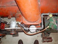
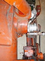
The pump is mounted under the front bumper right in front of the front axle's differential. It hangs down in front of the axle using a half-inch thick plate. This plate hangs vertically and the additional bearings mention later are connected to a horizontal leg that I welded to the plate. The pto shaft is under the axle as well. It connects to a cardigan-joint rated at 20hp. This sits between the pump and the stub shaft that is held by two pillow blocks. The pump is a bit low to the ground but it's protected by the big plate. I'd say it's about 6 inches above the ground. As long as we don't go off-roading, we'll be ok. Then again, that statement is true for my blower too, due to the Kubota sub-frame.
The double pillow block set up holds the business end of the pto shaft U-joint and the stub shaft. The pto shaft is about 48 inches long and connects to the mid-pto outlet under the driver. There is a third pillow block half way along the pto shaft to prevent any wobbling of the middle of the shaft. This means the shaft is held at both ends and in its middle.
The pump is made by Prince and the motor by Cross. I'll get the model numbers... I think the displacements are about 2.25 for both pump and motor. We really didn't need much power the blower unit is only about 44 inches wide. I think it was designed for clearing sidewalks back in the early 1980's. The maximum pump RPM is 3000 but we designed everything to run at 2600 RPM max and 2000 typical.
I forget how I picked the motor. I think I ran the design calculations from two directions and found an optimal mid point in the power needed vs. the power available. I picked a motor that could handle the 80/20 rule. As it turns out, this motor will handle far more power than this tractor can supply. If everthing were to come to a grinding halt, the tractor would stall before the motor or pump would reach their relative maximum pressures or torque loads.
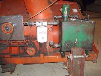
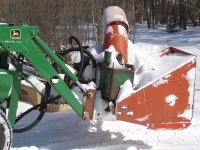
Regarding the size of the motor, the photo is fooling your eye. It's a typical size for handling about 20 hp; about the size of a softball. Oh and it's a gearmotor; so's the pump. We are only dealing with about 18 gallons per minute max so things are still small and gearmotors are great for that sort of size. The motor has an external atmospheric drain. Some motors have internal drains. This one allowed for either condition except for our setup. The motor literature said an external drain was necessary if running continuously near the high RPM limit. That's us, so I put one on.
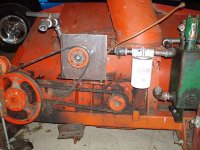
The pulley is a taper lock type that locks to an adapter that fits the bore of the pulley and motor shaft. I think we had to increase the bore size in the pulley to fit the adapter. I think we only needed a 1/16 or so. The pulley came with the blower, we bought the adapter. I
ncidently, the blower was originally driven by a PTO shaft from a mowing tractor. Its was one of those tractors that looks like it's going backwards all the time. We use the same two drive belts and tensioner.
The pump stays on the tractor during the winter. We use oversized quick disconnects from the trucking industry. They flow a little better especially on the suction side of the pump. The hydraulic system is a little small for my taste, but that's what we had available. The tank, hoses and components hold 5 gallons. I'm sure we get some foam built up in the top of the tank, but I think we are ok considering the amount of use it's getting (about two hours this season).
I don't anticipate moving the hydraulics to the tractor. The owner has no other use for 20hp worth of hydraulics so it'll stay as is. We still need to add a relief valve though. Not having that bugs me a little. I figure the belts will slip before the unit builds 3000 psi. ...fingers crossed.