42/43/4400 Valve Adjustment Procedure

   / 42/43/4400 Valve Adjustment Procedure #1  

arrabil

Veteran Member
Joined
Jul 3, 2008
Messages
1,019
Location
Winterstown, PA
Tractor
JD 4200 & X475
In case anyone is interested....

This definitely applies to the 4200, 4300, and 4400. I imagine it applies to all 4200-4710 tractors and the new 3000/4000 series but I can't verify that.

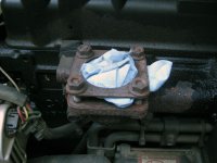
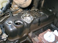
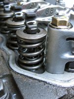
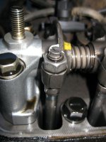
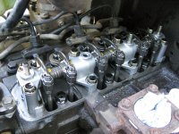
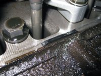
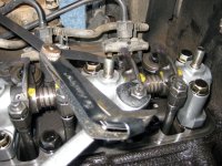
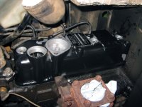
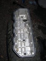
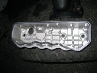
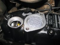
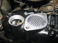
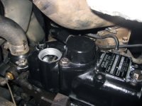
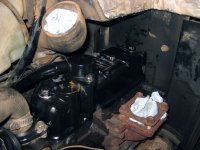
So, I had a bad leak at the valve cover somewhere. Deere calls it the rocker arm cover. I adjusted the valves while I had it off (good suggestion dfkrug).

The Deere instructions are attached. Pictures follow.
 

Attachments

  • 42-43-4400 Valve Adjustment.pdf
    178.4 KB · Views: 855
   / 42/43/4400 Valve Adjustment Procedure
  • Thread Starter
#2  
You have the option of power washing the engine before you start disassembly. Or using an engine cleaner with a regular water hose. I blew the engine off with the air compressor. No matter which route you choose, make sure you get behind the engine and into every nook and cranny.

First the muffler need to be removed. Four bolts. I stuffed a paper towel into the hole and sealed it with the gasket and nuts. Don't want anything getting in there while you're working.

Then the airbox comes out. Three bolts and a hose clamp. You need to loosen the two bracket bolts that attached the box to the engine air intake. They don't need to be removed as the airbox bracket just slides under them. The third bolt needs to be removed completely. The hose clamp that connects to the engine air intake needs to be loosened to get the airbox out. Stuff a rag into that hose too to prevent contamination. When everything is loose, wiggle the airbox out.
 

Attachments

  • muffler1.jpg
    muffler1.jpg
    171.7 KB · Views: 318
  • airbox1.jpg
    airbox1.jpg
    135.5 KB · Views: 290
  • airbox2.jpg
    airbox2.jpg
    184.1 KB · Views: 259
  • airbox3.jpg
    airbox3.jpg
    146.3 KB · Views: 307
   / 42/43/4400 Valve Adjustment Procedure
  • Thread Starter
#3  
Next you remove the breather cap. Two bolts. You can see the breather plate and the breather baffle under that. There was a lot of oil under the cap o-ring. The o-ring was shot. Good clue as to why there might be a leak.

The breather baffle (the Brillo pad type stuff) was also poorly installed. Part of the hole down to the engine was open. Another good sign as to where the leak is coming from.

Next I removed the oil cap and the three valve cover bolts. The valve cover bolt o-rings were also shot. Wow, maybe its leaking from multiple places.
 

Attachments

  • valvecover1.jpg
    valvecover1.jpg
    246.8 KB · Views: 456
  • breather2.jpg
    breather2.jpg
    217.3 KB · Views: 352
  • breather1.jpg
    breather1.jpg
    205.8 KB · Views: 360
   / 42/43/4400 Valve Adjustment Procedure
  • Thread Starter
#4  
The valve cover comes off next. Lift up and out. I had to smack it lightly with a rubber mallet to make it unseal from the head.

You can see how the valve cover gasket didn't come off cleanly. The valve cover gasket was also shot. Anyone noticing a theme here? It looks like it was leaking at the back of the engine for sure. Getting happier I started on this project at this point.

You can see the valves and rockers with the cover removed. Two per cylinder, six total. You can also see the flat head stud that gets adjusted and the nut that holds the adjustment. You can also see the rocker and the valve seat where the clearance is set.

All six clearances were too loose on my engine. 0.006-0.010" is spec. Mine were all 0.013-0.015".
 

Attachments

  • valves3.jpg
    valves3.jpg
    228.7 KB · Views: 378
  • valves2.jpg
    valves2.jpg
    142.3 KB · Views: 553
  • valves1.jpg
    valves1.jpg
    234.2 KB · Views: 538
  • valvecovergasket1.jpg
    valvecovergasket1.jpg
    247 KB · Views: 338
   / 42/43/4400 Valve Adjustment Procedure
  • Thread Starter
#5  
Now we need to find Top Dead Center for cylinder 1 and adjust the valves. Cylinder 1 is towards the rear of the tractor. Cylinder 3 is at the front. The valves are adjusted in the order 1, 3, 2.

To set TDC on cylinder 1, you rotate the flywheel until the inspection hole shows the "1" mark lined up with the mark on the transmission tunnel. You're supposed to rotate the engine by the crank pulley bolt with a 17mm socket. First problem with the instructions: my nut was 19mm. Second, everything is in the way of making this happen easily. So I just pushed on the fan to rotate the engine. Surprisingly that worked like a charm.

Now can anyone guess where the inspection hole is? It only took me an hour to find it. From under the tractor you can see a hole that looks like it would line up perfectly with the flywheel so you can see easily. But the hole is covered by a loader mounting frame. Well, that doesn't change the fact that its the flywheel inspection hole!!! So off comes the loader mount. So glad that turned out to be it!

Second problem with the instructions: they mention a mark on the transmission tunnel. There is no mark! Like the picture shows, you line up the "1" mark with the center of the hole. Oooh, precision.
 

Attachments

  • inspectionhole1.jpg
    inspectionhole1.jpg
    205.6 KB · Views: 460
  • inspectionhole2.jpg
    inspectionhole2.jpg
    122.5 KB · Views: 446
   / 42/43/4400 Valve Adjustment Procedure
  • Thread Starter
#6  
At this point you adjust the valve clearance. I used 0.008" as the spec. Why? My feeler gauge has 0.008" and 0.010" and I wanted them as tight as possible.

First you loosen the nut with a wrench. Third problem with the instructions: they tell you the nut is 10mm, mine were 12mm.

Then you loosen the stud with the flathead screwdriver top. They tell you to use a flathead screwdriver. I always use my fingers. It shouldn't be tight at all. Loosen the stud very, very little. Just to make it so the stud and nut will move independently of each other. If you loosen it too much, you'll need to check the valve seat (which you should actually do anyway) because it will almost certainly come out of position.

Slide the feeler gauge in between the rocker arm and the valve cap and tighten the stud until the feeler is in there really tight but still moveable. If you're using 0.006" then you want a slightly loose fit. Then tighten the nut but not all the way. Slide the feeler gauge in and out and be confident its at the right setting. Readjust if necessary. With the feeler gauge still in place (this is important so the stud doesn't move), tighten the nut completely. Check again that the clearance is right. Check the next size up to make sure it does NOT fit. If everything is right, move on to the second valve.

When both valves for cylinder 1 are done, do cylinder 3. Then cylinder 2. Its actually not hard at all. After the first one you'll be an expert.
 

Attachments

  • valveclearance1.jpg
    valveclearance1.jpg
    229.8 KB · Views: 544
   / 42/43/4400 Valve Adjustment Procedure
  • Thread Starter
#7  
Time for reassembly...

I cleaned the valve cover really well. Then I cleaned the gasket opening even better. I put some oil all the way around the groove and installed the gasket while smoothing the oil over top of the gasket.

Gently install the cover back on the engine. Then tighten the three valve cover bolts. I used three new valve cover bolt o-rings. The originals were shot (big surprise).
 

Attachments

  • valvecover4.jpg
    valvecover4.jpg
    195.1 KB · Views: 337
  • valvecover3.jpg
    valvecover3.jpg
    166.3 KB · Views: 269
  • valvecover2.jpg
    valvecover2.jpg
    156.1 KB · Views: 284
Last edited:
   / 42/43/4400 Valve Adjustment Procedure
  • Thread Starter
#8  
You can see the new baffle versus the old baffle. I was going to return the new baffle after first seeing it but after looking at the old baffle I decided I would use it. I installed the baffle better then the original was installed. Or so I think. I made sure to cover the opening better anyway.

The plate gets installed next. I cleaned it well too.

I installed a new breather cap o-ring. I rubbed it in some oil as well.

And finally the breather cap itself. I cleaned it very well too. I really need this stuff to be clean so I can see if there are any leaks after a few hours.
 

Attachments

  • breather3.jpg
    breather3.jpg
    250.9 KB · Views: 283
  • breather4.jpg
    breather4.jpg
    170 KB · Views: 266
  • breather5.jpg
    breather5.jpg
    172.6 KB · Views: 314
  • breather6.jpg
    breather6.jpg
    175.4 KB · Views: 419
   / 42/43/4400 Valve Adjustment Procedure
  • Thread Starter
#9  
And the finished product.

Well kind of. I plan on removing the exhaust manifold to clean it. Mostly so I can spot any new leakage easily but also because I'd like to change the gasket. I'm just guessing but its probably in as bad a shape as every other gasket and o-ring I just replaced.

And got to finish reassembly of the exhaust and the loader mount.

I installed a new o-ring on the oil cap. I take it everyone knows why. :D

You can see where I loosened the hose clamp to remove the airbox here too.

The parts list:
Muffler gasket (M805832, $6.59)
Exhaust manifold gasket (M808644, $4.44)
Breather cap o-ring (M801034, $2.31)
Breather cap baffle (M801032, $4.10)
Valve cover o-ring (M801036, $10.35)
Valve cover bolt o-ring (CH10568, $0.61, x3)
Oil cap o-ring (M805711, $2.05)
 

Attachments

  • valvecover5.jpg
    valvecover5.jpg
    184.7 KB · Views: 361
   / 42/43/4400 Valve Adjustment Procedure #10  
EXCELLENT THREAD!

I'm 100-hours overdue on this chore.

I didn't know there was an oil filler cap on the valve cover as I've always used the one on the right side of the engine; but it makes sense there is one where this motor is used in other applications.

How many hours does your tractor have on it? Mine has about 610 and I need to do a 200-hour service too.

About how long did it take you to do valve adjustment?

That sucks that the right loader mount has to come off. I have my canopy's front posts mounted to them.

At least the parts are reasonable and the fuel tank didn't have to come out. Thank good ness for small favors.
 
 
Top