Electric Selector Valve Install

   / Electric Selector Valve Install #1  

MikeyB

Silver Member
Joined
Oct 11, 2006
Messages
134
Location
Parker,CO
Tractor
JD 3320
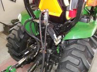
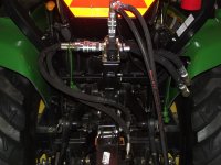
Well, its not pretty but it works! I installed an electric selector valve at the rear of the tractor to have 2 working hydraulic circuits. Right now, I have the hydraulic top link and snow chute rotation. Maybe if I am good Santa will bring
me a hydraulic sidelink or a cylinder for my back blade. :laughing:

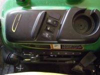
The valve was a fairly easy install. The valve and fittings came from Surplus Center, and the electric switch is a JD strobe light switch. The switch fit in the console perfectly but I was unable to figure out how to get it to light up when I have the switch on. Anyone have a pin out for the switch? I am fairly certain it came from a cabbed tractor and was the only switch the dealer had in stock.

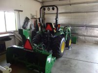
Overall, it was a fun project except for getting teflon paste on everything when preparing all the fittings! Now I just need some snow to try it out!

Mike
 

Attachments

  • 004.jpg
    004.jpg
    894.6 KB · Views: 676
  • 009.JPG
    009.JPG
    818.8 KB · Views: 597
  • 008.JPG
    008.JPG
    846.5 KB · Views: 531
  • 002.jpg
    002.jpg
    817 KB · Views: 539
   / Electric Selector Valve Install #2  
That's pretty sweet- any details on the diverter and how you mounted it. I installed a 3rd SCV on my 3320 for a HTL- but sure wouldn't mind being able to tilt with a hydraulic as well.
 
   / Electric Selector Valve Install
  • Thread Starter
#3  
That's pretty sweet- any details on the diverter and how you mounted it. I installed a 3rd SCV on my 3320 for a HTL- but sure wouldn't mind being able to tilt with a hydraulic as well.

The valve was this from Surplus Center:
https://www.surpluscenter.com/item.asp?item=9-7852&catname=hydraulic
and it works great.

I actually mounted it on the top of the bracket that held the manually adjustable top link when changing implements. There were already two holes in the bracket and I just drilled and tapped a metal plate that sits on top. The valve has two thru holes in the body and I bolted that to the plate. With my existing hose lengths this seemed to work best. Hoses are expensive and I didn't want to have any more made if I could avoid it.

With the switch off my toplink works, with the switch on my snow blower chute rotator works. When snow season is over I plan to get a sidelink and maybe a cylinder to angle my back blade. Problem is, with two functions I think about what I could do with 3! Top Link, side link, blade angle, etc...
It is neverending!:confused2:

Let me know if I can be any help,
Mike
 
Last edited:
   / Electric Selector Valve Install #4  
Certainly smaller QC's would be in order, and maybe even smaller hyd. hose. That would trim it down some (sans your apology for "not pretty").
Important thing is it works. :)
 
   / Electric Selector Valve Install
  • Thread Starter
#5  
Yes, definitely not pretty! But I wanted to stay with the generic Pioneer QC's so everything would be interchangeable. The hose sizes are a mess. The toplink had 1/4, the blower 3/8, and the inputs were 1/2" so I just left it alone to prevent having to buy a bunch of extra adapters or new expensive hoses.

Mike
 
   / Electric Selector Valve Install #6  
Nice job mike...I bet in time you'll think of a way to clean it up a little. One things is for sure-I have seen A LOT worse 'round here before! You could change the hose on the blower-no need for it to be 3/8", 1/2" is perfect. For the feed into the valve, 3/8" is perfect.

Yon can stack these diverters together for more circuits, Bbut I am not sure how that really works.

The switch should have a extra terminal on it-I think it needs to be grounded for the light to work.

How was wiring that Hirshman?
 
   / Electric Selector Valve Install
  • Thread Starter
#7  
kennyd said:
Nice job mike...I bet in time you'll think of a way to clean it up a little. One things is for sure-I have seen A LOT worse 'round here before! You could change the hose on the blower-no need for it to be 3/8", 1/2" is perfect. For the feed into the valve, 3/8" is perfect.

Yon can stack these diverters together for more circuits, Bbut I am not sure how that really works.

The switch should have a extra terminal on it-I think it needs to be grounded for the light to work.

How was wiring that Hirshman?

Thanks for your help KennyD!
Hirschmann connector made perfect sense once I had it in my hands and could actually look at it.
The 18/2 wire was perfect.

The switch has 4 terminals. I used a voltmeter and tried all the combinations I could think of and
still never got it to work. Even made pigtails and tried different setups and still a no-go. The switch
works which is the important thing I guess but I'm sure I'll get it working eventually.

Thanks again,
Mike
 
   / Electric Selector Valve Install #8  
Mike, Could you post a couple of pics of the top link? I bought a swivel end cylinder that I use for top link but had to remove the bracket you used for mounting, for clearance of the fittings. I would like to see yours. I am still in the idea phase for my divertor. :thumbsup:Thanks Matt
 
   / Electric Selector Valve Install
  • Thread Starter
#9  
mfreund said:
Mike, Could you post a couple of pics of the top link? I bought a swivel end cylinder that I use for top link but had to remove the bracket you used for mounting, for clearance of the fittings. I would like to see yours. I am still in the idea phase for my divertor. :thumbsup:Thanks Matt

Matt,

I will try and get some pix tomorrow. I am using the cylinder from Deere's TNT kit. They had one
Laying around the dealership. My cylinder is connected on the bottom hole on the tractor side. If you
still have clearance issues I wonder if the bracket could be turned around and rebent to you liking?

Regards,
Mike
 
   / Electric Selector Valve Install #10  
Looks good MikeB,

I can tell you exactly how that switch needs to be wired, as I just installed one for my strobes on my 3520 cab. The two prongs at the top of the switch require a hot and a ground. The hot will come from jumping your non-constant power on the switch itself. In plain english, the terminal that becomes hot when you turn the switch on. I will not matter which one you put the ground on or the hot on. I have included a very quick sketch. The red will be your constant hot, the yellow will be to whatever you want to power on with the switch. And lastly the black will be ground and the other yellow will jumper to the yellow on the switch. A diode is a good idea, but not a must. Without the diode you will get a glow on the toggle light for a few seconds until it uses the line energy up, then it will go out. I hope that helps.


Chad
 
 
Top