Help Interpreting Wiring Diagram & Using Multimeter

   / Help Interpreting Wiring Diagram & Using Multimeter #1  

sriddle1

Silver Member
Joined
Apr 2, 2014
Messages
212
Location
SW New Hampshire
Tractor
ACTIVE: JDX730 DAYS GONE BY: JD3010, JD790, JD425
Good Morning,

A cool crisp morning in SW New Hampshire BUT PLEASE SEND RAIN........

I'm trying to test out the voltage readings coming to the Stop Fuel Solenoid. I'VE attached the appropriate Wiring Diagram for my '05 JD 790 Production/Serial Number. Wondering if someone could walk me thru the Multi-Meter Red/Black Probe placements and readings I should get. I can see by my "un-trained" eye the White-Red-Black wire connector coming from the Solenoid connects to a Harness Connector - Solenoid White Wire connects to Harness White/Blue wire to "Time Delay Control Module" PN: M803344 + "K2" Fuel Relay. The RED coming off the Solenoid connects to Harness Green/White to "K2" Fuel Relay. If I disconnect the Solenoid Connector, place the Tractor in the Start Position, what readings should I get from the Harness side connector points. Please spoon feed me where I need to place the probes while taking measurements. If the readings at the Harness are good I would "Assume" (you know that they say about that) the Fuel Solenoid is Bad. If the readings aren't good then again I can assume the "Time Delay Control Module" PN: M803344 upstream is bad.......
 

Attachments

  • 790 Wiring Diagram 1.pdf
    352.6 KB · Views: 561
Last edited:
   / Help Interpreting Wiring Diagram & Using Multimeter
  • Thread Starter
#2  
YANMAR DIESEL 3TNV82A vs. 3TNE82A

Based on this thread went to the John Deere Parts Catalog to look up the PN for the Fuel Stop Solenoid. My Tractor is an '05 with Engine (as marked) "3TNV82A-LJNT". The Catalog lists PN: M806808 for the Solenoid & RG60092 for the O-Ring but there are REMARKS = (ENGINE MARKED 3TNE84 AND 3TNE82A). Can someone tell me what the "NV" vs. "NE" variation is. THANKS
 
   / Help Interpreting Wiring Diagram & Using Multimeter #3  
Re: HELP INTERPRETING WIRING DIAGRAM & USING MULTIMETER

Good Morning,

A cool crisp morning in SW New Hampshire BUT PLEASE SEND RAIN........

Looking at this thread you'll see I'm trying to test out the voltage readings coming to the Stop Fuel Solenoid. In my previous post I attached the appropriate Wiring Diagram for my '05 Production/Serial Number. Wondering if someone could walk me thru the Multi-Meter Red/Black Probe placements and readings I should get. I can see by my "un-trained" eye the White-Red-Black wire connector coming from the Solenoid connects to a Harness Connector - Solenoid White Wire connects to Harness White/Blue wire to "Time Delay Control Module" PN: M803344 + "K2" Fuel Relay. The RED coming off the Solenoid connects to Harness Green/White to "K2" Fuel Relay. If I disconnect the Solenoid Connector, place the Tractor in the Start Position, what readings should I get from the Harness side connector points. Please spoon feed me where I need to place the probes while taking measurements. If the readings at the Harness are good I would "Assume" (you know that they say about that) the Fuel Solenoid is Bad. If the readings aren't good then again I can assume the "Time Delay Control Module" PN: M803344 upstream is bad.......

Looked at my jd4200 solenoid. Face on the three contacts mak a triangle. The apex of the triangle contact should be ground. Of course I noted and then promptly forgot the lead colour.
 
   / Help Interpreting Wiring Diagram & Using Multimeter #4  
Good Morning,

A cool crisp morning in SW New Hampshire BUT PLEASE SEND RAIN........

I'm trying to test out the voltage readings coming to the Stop Fuel Solenoid. I'VE attached the appropriate Wiring Diagram for my '05 JD 790 Production/Serial Number. Wondering if someone could walk me thru the Multi-Meter Red/Black Probe placements and readings I should get. I can see by my "un-trained" eye the White-Red-Black wire connector coming from the Solenoid connects to a Harness Connector - Solenoid White Wire connects to Harness White/Blue wire to "Time Delay Control Module" PN: M803344 + "K2" Fuel Relay. The RED coming off the Solenoid connects to Harness Green/White to "K2" Fuel Relay. If I disconnect the Solenoid Connector, place the Tractor in the Start Position, what readings should I get from the Harness side connector points. Please spoon feed me where I need to place the probes while taking measurements. If the readings at the Harness are good I would "Assume" (you know that they say about that) the Fuel Solenoid is Bad. If the readings aren't good then again I can assume the "Time Delay Control Module" PN: M803344 upstream is bad.......


The fuel shut off solenoid colors red, white, black are:
Red = Pull in coil
White = Hold in coil
Black = Ground

Make sure PTO switch is OFF. Tractor is in Neutral. Your meter is set for DC volts in the correct range for 12-13 volts.

Start by checking your meter across the battery to make sure it is set correctly. Red to +, black to - you should have 12-13 volts.

Next check the harness side connector that goes to black on the FS (fuel shutoff). Red to battery + Black to black harness connector. If the harness black (ground wires is good, you should get 12-13 volts.

Now check the wire that matches up to the Red of the FS, (Green/White). Black meter lead to black wire of the connector. Red meter lead to wire that matches Red (Green/White) of the connector. PTO OFF, Neutral, Key ON. You should get 12-13 volts. This for the "hold in" coil of the FS

Now check the wire that matches up to the White of the FS (White/Blue). Black meter lead to black wire of the connector. Red meter lead to wire that matches White (White/Blue) of the connector. PTO OFF, Neutral. Key START. You should get 12-13 volts for ONE SECOND. This is the "pull in"
coil of the FS

If Black wire test fails, repair ground, black wire connects to ground.

If Red wire test fails, I would suspect the Delay Module

If White wire test fails I would suspect Fuel Relay, then Delay Module.

If all wires test OK suspect FS
 
   / Help Interpreting Wiring Diagram & Using Multimeter #5  
^^^^^

What he said... Z5, excellent explanation.
 
   / Help Interpreting Wiring Diagram & Using Multimeter
  • Thread Starter
#6  
Zebrafive, PERFECT & MUCH APPRECIATED. I originally started this request for help under the "790 Sporadic Starting" before asking a PM to move it out to this forum for wider review, glad I did. I am not mechanically inclined so thank you for the detailed step by step process. If you go to the "790 Sporadic Starting" Thread you'll see a reply saying it would be very hard, almost impossible, to take readings as you described. I value your input. THANK YOU AGAIN for responding..........
 
   / Help Interpreting Wiring Diagram & Using Multimeter
  • Thread Starter
#7  
Zebrafive, Thanks for the post,

I got a little behind the curve with two threads going at once, (I should have closed the old one "790 Sporadic Starting" right away after the PM created this thread on my request). :duh:

If I had I would have caught your post before I pulled the solenoid so now I'm faced with either disconnecting the starter tomorrow (per the old thread approach) and visually inspecting the Solenoid's plunger performance or re-install and going your route. I also mentioned when I manually pushed in the plunger on the solenoid I heard some slight gurgling noise.......

About your post, again THANK YOU for the detail, reads like a Fault Detect Fault Isolate (FDFI) Tech Manual Procedure which I need.........

You Wrote: Next check the harness side connector that goes to black on the FS (fuel shutoff). Red to battery + Black to black harness connector. If the harness black (ground wires is good, you should get 12-13 volts.

Question on the "Red to Battery" statement I'm getting a bit lost, my obsolete multimeter has (2) 16" test leads, in order to span that width I guess I'd have to connect a booster cable to the Battery + so I can place the probe on the battery + and Black to black harness connector ? I noticed you were very exact stating: PTO OFF, Neutral, Key "ON" or KEY in "START" Position for the other steps, this step is done with the tractor off.
 
   / Help Interpreting Wiring Diagram & Using Multimeter #8  
Zebrafive, Thanks for the post,

I got a little behind the curve with two threads going at once, (I should have closed the old one "790 Sporadic Starting" right away after the PM created this thread on my request). :duh:

If I had I would have caught your post before I pulled the solenoid so now I'm faced with either disconnecting the starter tomorrow (per the old thread approach) and visually inspecting the Solenoid's plunger performance or re-install and going your route. I also mentioned when I manually pushed in the plunger on the solenoid I heard some slight gurgling noise.......

About your post, again THANK YOU for the detail, reads like a Fault Detect Fault Isolate (FDFI) Tech Manual Procedure which I need.........

You Wrote: Next check the harness side connector that goes to black on the FS (fuel shutoff). Red to battery + Black to black harness connector. If the harness black (ground wires is good, you should get 12-13 volts.

Question on the "Red to Battery" statement I'm getting a bit lost, my obsolete multimeter has (2) 16" test leads, in order to span that width I guess I'd have to connect a booster cable to the Battery + so I can place the probe on the battery + and Black to black harness connector ? I noticed you were very exact stating: PTO OFF, Neutral, Key "ON" or KEY in "START" Position for the other steps, this step is done with the tractor off.

Yes, tractor can be OFF to do this step. You are confirming the black wire to ground is not broken. If you have a test light it would also work. Clip to battery + then the probe to the black wire. Light should come on.

If your leads are not long enough a jumper wire may be used.
 
   / Help Interpreting Wiring Diagram & Using Multimeter #9  
And make sure you use the right inputs on the meter.... You do not want your positive lead plugged into the Amperage position. It will blow the fuse in the meter.
 
   / Help Interpreting Wiring Diagram & Using Multimeter
  • Thread Starter
#10  
And make sure you use the right inputs on the meter.... You do not want your positive lead plugged into the Amperage position. It will blow the fuse in the meter.

tcartwri, Thanks for the reminder...... Because I'm weak in this space so I went on-line and found the User Manual for the old Multimeter. I checked it over, tuned-it, replaced the battery and read very closely the "Taking DC Measurements", I'm glad to report so-far-so-good but I do agree someone like me should be reminded of the simple things, you never know......I have to admit, I did wince a bit when I first placed the probes on the battery terminals, involuntary response.......

Zebrafive, I did the "meter across the battery" A-OK, 12-13 volts. Performed the "confirming the black wire to ground is not broken" A-OK 12-13 volts. Performed the ""hold in" coil of the FS" A-OK, 12-13 volts.

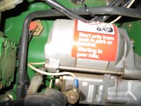
Now I'm at the juncture, visual check of Solenoid plunger or continue down the FD/FI Procedures you outlined. Since I have the Solenoid removed I want to first disable the starter. In a previous post, dieselcrawler recommended to remove the white wire from the starter, again, just to be sure I've attached a PIC of what I believe he is referring to. Once removed the starter will not spin with the ignition key set to position "START"......

Once I get confirmation on the White Wire (pictured) I will remove it then take your FD/FI Measurements to make sure the GAA-ZINS are coming in right to the harness and the Time Delay Module has not fail (Red Wire Test). If all is A-OK then I'll replug the solenoid into the harness connector and proceed with visual observation.....

QUESTION: Is there something special I should be looking for with the plunger retraction..... If that operates OK then maybe the gurgling I described with visible oil around the plunger shaft as I push it in indicates the solenoid is in trouble.
 

Attachments

  • IMG_6978.JPG
    IMG_6978.JPG
    1.5 MB · Views: 392
 
Top