B2620 Cab Installation and Modifications

   / B2620 Cab Installation and Modifications #1  

ericdube

Gold Member
Joined
May 31, 2010
Messages
333
Location
Massachusetts
Tractor
Kubota L4760
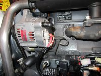
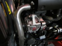
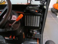
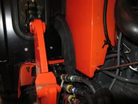
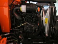
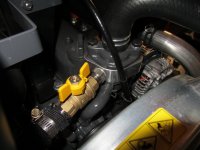
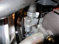
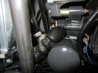
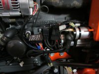
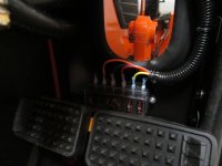
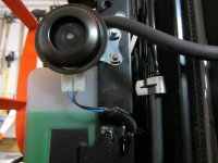
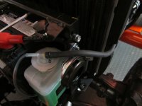
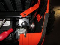
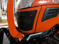
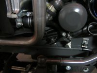
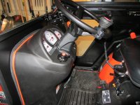
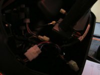
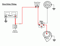
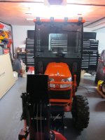
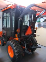
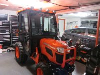
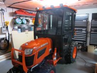
I've been busy over the last few months getting my B2620 ready for snow blowing this winter including installing a Sims Indy Cab on my B2620 (that I bought at the beginning of this year) along with a number of other modifications (horn, alternator, electrical wiring, heat, LED lighting, control switches, etc.)

While I still haven't finished everything, I figured I'd finally get around to starting a thread so I can post pictures of everything. Also, I should have some better pictures of the cab installation once I finish up the LED lighting this weekend.

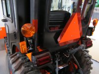
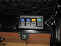
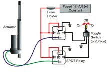
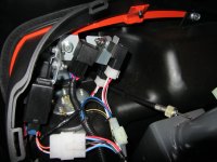
For the LED Lighting I used Rigid Industries Dually D2 (x4) Driving Spot Lights in the front and Dually (x2) Diffused Lights in the rear. Both sets of lights are switchable from the in-cab switch panel. The lights are really bright and use very little amperage (albeit a bit pricey though.)
 

Attachments

  • cab1.JPG
    cab1.JPG
    258.8 KB · Views: 886
  • cab2.JPG
    cab2.JPG
    266.3 KB · Views: 886
  • cab3.JPG
    cab3.JPG
    290.7 KB · Views: 850
  • cab4.JPG
    cab4.JPG
    303.8 KB · Views: 1,573
Last edited:
   / B2620 Cab Installation and Modifications
  • Thread Starter
#2  
More pictures of the cab including the upgraded 3-point hitch assembly from the xx30 series, and the 40-amp high capacity alternator. The Sims cab comes with rear light brackets to relocate the round lights (although you need to build your own wire extensions to plug them in.)
 

Attachments

  • alternator2.JPG
    alternator2.JPG
    376.8 KB · Views: 687
  • alternator1.JPG
    alternator1.JPG
    263.3 KB · Views: 1,047
  • cab6.JPG
    cab6.JPG
    245.9 KB · Views: 3,419
  • cab5.JPG
    cab5.JPG
    286.7 KB · Views: 651
Last edited:
   / B2620 Cab Installation and Modifications
  • Thread Starter
#3  
Pictures of the cab heater installation. I had to source a number of parts shown in the pictures since they didn't come with the Sims Heater installation kit and many of the original parts didn't work for the B2620 due to the hood support mechanism (major design flaw by Sims in my opinion.)

I ended up getting my own shutoff valve and 3/8" to 1/2" adapter to connect to the manifold that Sims provided.

To protect the hoses from chaffing I used hydraulic hose covering. It worked great and doesn't take up much space.
Also, the heater has a dual-speed blower behind it that can be controlled from the switch control panel.

Finally, I used the original hole where the heater switch was suppose to go to install a Powerlet outlet in-place of that, which powers a monitor providing voltmeter, thermometer, and clock (just above the heater.)
 

Attachments

  • heat1.JPG
    heat1.JPG
    276.8 KB · Views: 834
  • heat2.JPG
    heat2.JPG
    296.9 KB · Views: 908
  • heat3.JPG
    heat3.JPG
    246.3 KB · Views: 1,461
  • heat4.JPG
    heat4.JPG
    258.4 KB · Views: 677
Last edited:
   / B2620 Cab Installation and Modifications
  • Thread Starter
#4  
More pictures of the heater installation. You need to cut the lower radiator hose in the middle and install a T-fitting.
 

Attachments

  • heat5.JPG
    heat5.JPG
    216.4 KB · Views: 673
  • heat6.JPG
    heat6.JPG
    309.4 KB · Views: 598
Last edited:
   / B2620 Cab Installation and Modifications
  • Thread Starter
#5  
Pictures of the electrical installation. I made a custom bracket in the engine bay to mount a 50-amp Bosch relay with a 40-amp fuse to switch the accessories on/off with the ignition key.

The switch control panel was an option from Sims, but I wouldn't recommend buying it. It isn't designed to fit this cab, and I had to modify the bracket just to make it fit. In addition, the wiring harness is useless - I ended up cutting it up into pieces and built my own with the wiring. In the end, it would have been much cheaper to build my own.

The switches control the front LED lights, rear LED lights, Mini LED Lightbar (not shown), and dual-speed heater blower motor.

If you look closely at the last picture, you can make out the engine block heater plug on the bottom. It gets installed in the engine on this side.
 

Attachments

  • electrical3.JPG
    electrical3.JPG
    266.4 KB · Views: 618
  • electrical2.JPG
    electrical2.JPG
    229 KB · Views: 551
  • electrical1.JPG
    electrical1.JPG
    311.7 KB · Views: 730
Last edited:
   / B2620 Cab Installation and Modifications
  • Thread Starter
#6  
I attached a handle bar mounted ATV winch rocker switch to the hydraulic joystick using a 1/2" SS split collar ring for the chute angle adjust. Unfortunately, these switches (while compact) are SPDT so you need to use a dual relay setup. I made a custom bracket and mounted a pair of relays under the seat with waterproof disconnects for everything including SAE connectors going to the snow blower.

Also, attached is the wiring diagram that I used to wire the pair of relays. To make things easly, I ended up buying two un-wired relay sockets and made all the wiring terminations myself. This allowed me to attach all the ground together and daisy chain the connections to all I had to attach was a single ground and positive connection.
 

Attachments

  • switch1.JPG
    switch1.JPG
    231.3 KB · Views: 463
  • switch2.JPG
    switch2.JPG
    324.6 KB · Views: 401
  • switch3.JPG
    switch3.JPG
    235.1 KB · Views: 419
  • actuator_relays.jpg
    actuator_relays.jpg
    49.3 KB · Views: 993
Last edited:
   / B2620 Cab Installation and Modifications
  • Thread Starter
#7  
The horn kit was from the B26 (P/N L8043). It's practically a bolt-on kit with the exception that you need to build your own wiring harness from the combination switch to the horn relay (I used a Bosch 40-amp relay for this). The only other part I needed to buy from Kubota was the combination switch (P/N 32741-55420)

The rest of the parts (other than the Bosch 40-Amp Relay (0 332 019 157) which I got from Ebay) I bought directly from Eastern Beaver. You'll need two .090" MT female terminals, a 2-position .25" female connector/terminals (for connecting into the wire harness that comes with the horn kit), and a 5-pin relay socket for the Bosch relay.

The horn mounts on the left side of the tractor where there's two existing holes that line up perfectly with the horn holes. It even clears the front grill without any issues. My guess is that this is where the horn suppose to go (it's too perfect!)
 

Attachments

  • horn4.JPG
    horn4.JPG
    251 KB · Views: 434
  • horn3.JPG
    horn3.JPG
    242.4 KB · Views: 377
  • horn2.JPG
    horn2.JPG
    257.6 KB · Views: 484
  • horn1.JPG
    horn1.JPG
    277 KB · Views: 411
Last edited:
   / B2620 Cab Installation and Modifications
  • Thread Starter
#8  
More pictures of the horn installation including the connectors which I sourced from Eastern Beaver so I didn't have to modify any of the existing wiring (basically everything was plug and play - no drilling or cutting of the existing Kubota wiring harness.)

Also, I attached the wiring diagram that I used to wire up the horn.
 

Attachments

  • horn5.JPG
    horn5.JPG
    236.5 KB · Views: 949
  • horn6.JPG
    horn6.JPG
    268.6 KB · Views: 404
  • horn8.JPG
    horn8.JPG
    345.6 KB · Views: 775
  • horn7.jpg
    horn7.jpg
    178.7 KB · Views: 347
  • HornWire.gif
    HornWire.gif
    5.7 KB · Views: 733
Last edited:
   / B2620 Cab Installation and Modifications #9  
Thats a Great Looking job you did!!

Enjoy the warmth!

Stu
 
   / B2620 Cab Installation and Modifications #10  
Very nice looking job.Looks like quite a bit of work.Will be a very nice setup for clearing snow I am sure.:thumbsup:
 
 
Top