I have a Kubota L2800 and L463 loader I have installed a non Kubota open center control valve and rear hydraulics. I got the plumbing info. from my local Kubota dealer. The dealer is incorrect. I have no pressure to the rear outlets. If anybody has the exact plumbing required for this it would be greatly appreciated. I can explain in more detail if someone has the specifics. Thanks lots John
You are using an out of date browser. It may not display this or other websites correctly.
You should upgrade or use an alternative browser.
You should upgrade or use an alternative browser.
adding a control valve and rear remotes to Kubota L2800 and LA 463 loader
- Thread starter farough99
- Start date
/ adding a control valve and rear remotes to Kubota L2800 and LA 463 loader
#1
J_J
Super Star Member
- Joined
- Sep 6, 2003
- Messages
- 18,928
- Location
- JACKSONVILLE, FL
- Tractor
- Power-Trac 1445, KUBOTA B-9200HST
Well, tell us what you did , maybe we can find a solution.
Did you use the PB from the loader or use the hyd block to input the remote valve?
Did you somehow block the return.
If remote is PB, did you use the PB adapter to pass fluid downstream?
Did you use the PB from the loader or use the hyd block to input the remote valve?
Did you somehow block the return.
If remote is PB, did you use the PB adapter to pass fluid downstream?
Well, tell us what you did , maybe we can find a solution.
Did you use the PB from the loader or use the hyd block to input the remote valve?
Did you somehow block the return.
If remote is PB, did you use the PB adapter to pass fluid downstream?
I have a L2800 and LA 463 loader I have tried to install 1 single control valve on the tractor and two rear hydraulic couplers at the rear of tractor. I purchased an open center valve. My plumbing is ran as follows from the Hydraulic block on the tractor under the right foot board. There are the 3 ports.
Top left port on tractor block hose tagged green in color "from implement" goes to right port on loader control block.
Top Right on tractor block hose tagged red in color "implement maximum flow" goes to left port on loader control block
Bottom on tractor block hose tagged gray in color from implement "tank port" goes to bottom port on loader control block
All above is factory plumbing. I do not believe I have mistakenly changed anything above
My Kubota dealer told me to remove the gray tank port hose from tractor block and connect it to the pressure port on new valve. then run hose from tank port on new valve to tractor block " tank port" thus in series. The two remaining ports on the new valve go to the quick couplers at the rear of the tractor. Using this method of plumbing my loader and 3pth work fine but have no pressure to rear. I will get pressure at rear when operating the loader valve in the curl up position only when it is curling. Once the curl cylinders are closed there is no more pressure at the rear. Obviously my Kubota dealer has given me wrong info. Can you please give me any instruction. Any info. would me much appreciated Thanks Lots John
J_J
Super Star Member
- Joined
- Sep 6, 2003
- Messages
- 18,928
- Location
- JACKSONVILLE, FL
- Tractor
- Power-Trac 1445, KUBOTA B-9200HST
Can you show some detailed pictures? Clear and up close.
Please use the IN, OUT , work ports designations when describing connecting points.
Using a tractor with open center tractor, the flow through all valves has to be in series and the fluid should flow through all valves in the neutral position.
Your connections should go something like this.
Pump, then FEL valve, FEL valve PB OUT to the next valve, eventually through the 3pt and then to tank. All return ports should go to tank.
Your pump might feed the hyd block and there are outlets from the hyd block to the loader valve.
Some hyd blocks have an adapter plate to give access to a set of in IN and OUT ports for remote valves.
The purpose of PB on any valve is to provide a path for fluid at low pressure with valves in neutral , or fluid at high pressure.
Tank line should be open to tank/reservoir.
The OUT/tank return port normally only passes the cyl fluid to tank.
J_J
Super Star Member
- Joined
- Sep 6, 2003
- Messages
- 18,928
- Location
- JACKSONVILLE, FL
- Tractor
- Power-Trac 1445, KUBOTA B-9200HST
Here is a similar post that we have been discussing about the hyd block.
Kubota L3130 Hydraulic accessory block - Page 2
You need to have the adapter plate on the hyd block that has the threaded ports for supply and PB return.
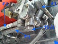
In the picture, #1 is input to the hyd block from the pump supply.
#2 PB out
#3 off the back of the hyd block is return to tank.
Hex bolt on bottom covers the relief valve.
The plate with the three bolts is a cover plate and you replace that with a plate with threaded ports, and this is your pressure and PB return line.
Kubota L3130 Hydraulic accessory block - Page 2
You need to have the adapter plate on the hyd block that has the threaded ports for supply and PB return.
In the picture, #1 is input to the hyd block from the pump supply.
#2 PB out
#3 off the back of the hyd block is return to tank.
Hex bolt on bottom covers the relief valve.
The plate with the three bolts is a cover plate and you replace that with a plate with threaded ports, and this is your pressure and PB return line.
Attachments
Last edited:
Chilly807
Elite Member
I did the same thing you're talking about with my L3400 with loader. I added one set of remotes and a non-Kubota valve to control the new remote. Here's the link to that thread..
http://www.tractorbynet.com/forums/hydraulics/188519-adding-rear-remote-kubota-l3400.html
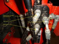
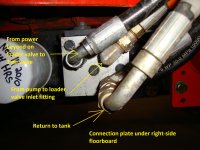
You should be able to see enough of the connection plate to help you out. I used the (green) hose from the power beyond connection on the loader valve to go to the inlet on the new remote valve, the outlet and power beyond adapter from the new valve attach where the green hose was connected on the junction block. The return or tank connection from the new valve is teed into the drain connection on the block. I think it's the grey connector. If you want I'll try to get a few more pics if you need them.
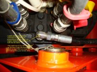
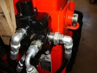
The first pic shows the upper left connection from the power beyond adaptor on the remote valve (second pic, yellow arrow) going to the 3 point hitch valve, which is third and last in line. The loader is first, the remote valve is 2nd, and the 3ph is last, which is nearly always the case. This is because there is no way to connect the 3ph valve outlet with a power beyond adapter since it's buried in the transmission case.
Sean
http://www.tractorbynet.com/forums/hydraulics/188519-adding-rear-remote-kubota-l3400.html
You should be able to see enough of the connection plate to help you out. I used the (green) hose from the power beyond connection on the loader valve to go to the inlet on the new remote valve, the outlet and power beyond adapter from the new valve attach where the green hose was connected on the junction block. The return or tank connection from the new valve is teed into the drain connection on the block. I think it's the grey connector. If you want I'll try to get a few more pics if you need them.
The first pic shows the upper left connection from the power beyond adaptor on the remote valve (second pic, yellow arrow) going to the 3 point hitch valve, which is third and last in line. The loader is first, the remote valve is 2nd, and the 3ph is last, which is nearly always the case. This is because there is no way to connect the 3ph valve outlet with a power beyond adapter since it's buried in the transmission case.
Sean
Attachments
Gordon Gould
Super Member
- Joined
- Apr 1, 2007
- Messages
- 6,227
- Location
- NorthEastern, VT
- Tractor
- Kubota L3010DT, Kubota M5640SUD, Dresser TD7G Dozer
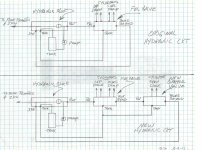
Here is a diagram of the way I added a valve to my L3010. My added valve had a power beyond port. If yours does not you would run your added valve tank port to the same spot that I ran the new valve power beyond output and you would ignor the tee'ed tank connection between the two valves on my diagram like Sean did.
Attachments
Sean Thank you so much for the info.I think i may have the wrong valve. My valve has the following ports. #1Pressure--- #2Tank--- plus the two that go to the quick couplers. If I am understanding correctly my valve should have 5 ports 1 for power beyond?? Following is the specs on the valve that I am using. By the way nice job. If you could let me know it would be appreciated. John
Function
3-Position, 4-Way, Open Center
Max. Continuous Pressure
3,750 PSI
Max. Continuous Flow
8 GPM
Peak Flow
12 GPM
Relief Valve Setting
2,100 PSI
Relief Valve Range
1,500 to 3,750 PSI
Inlet Port(s)
8 ORBF
Outlet Port(s)
8 ORBF
Work Ports
8 ORBF
Max. Return Line Pressure
1,100 PSI
Load Check(s)
One For Valve
Handle Mount
Vertical/Horizontal
Convertible To Closed Center
No
Convertible To Power Beyond
No
Convertible Spool Types
Motor, Single-Acting
Package Dimensions (L x W x H)
7.8" x 3.7" x 4.0"
Weight (lbs): 4.5
Further to my previous post. I just got everything working properly THANKS to you fellows. After I read all 3 posts thoroughly and made sense of Gordons drawing it worked. I thought I needed the power beyond valve but after getting Gordons diagram through my thick head it worked.I ran the tank port from the new valve to the top left 3ph on the tractor block and plumbed it as per the drawing and Sean's pictures. I really appreciate the help. I was starting to lose it. Now i can install my Kubota quick attach and try out my new 7 foot Bobcat front blade. You all saved my weekend. Thanks again fellows. JOHN
Chilly807
Elite Member
Hmm... have you tried operating the 3 point hitch yet? Possibly with any load on it? Unless I'm missing something, the valve "tank" connection you hooked to the 3PH (at the block) only has flow available when the remote valve is operating and oil is being returned from a cylinder or motor. In other words, you're using "second-hand" oil flow to operate your 3PH. I think you do need a different valve, one with 5 connections, those being "pressure in", "tank", "power beyond" (usually with an adapter) and the 2 work ports.
This is because the oil being returned from the cylinder or motor needs somewhere to go when the cylinder or motor is being operated. In this case, you have it flowing to the 3 point hitch instead of the tank. What I THINK will happen is that once the accessory cylinder is at it's maximum stroke (either extended or retracted), is that the 3 point hitch will stop lifting, since there's no more flow to it at that point. There's also the issue of back pressure on the remote valve. If you have a load on the 3PH and the valve calling for more oil, that load pressure will be felt at the tank port as well, and may bind the remote valve.
I hope I'm wrong, but I don't think so.
The way the power beyond system works, is that it is a series circuit in which the items that are first in the flow path take priority over those that come after them. 95% of these are plumbed with the loader coming first, the remote valves second, and the 3PH coming third in line. The 3PH is almost always the last item in line. When you're using the loader, if you're using all the oil flow (i.e. the valve is fully open), there is no oil flow to the remotes or the 3 PH. Same with the remote.. if it's fully opened there is no flow to the 3PH valve. This can be a problem if you're using a hydraulic motor to drive a spreader for example and want to raise the 3 PH while the spreader is running. I think a flow divider would work in that instance, but we're getting beyond where we need to be.
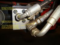
I've added some more pictures of my valve hookup. Just in case. From what I can see, Gordon's is virtually identical to mine.
Sean
This is because the oil being returned from the cylinder or motor needs somewhere to go when the cylinder or motor is being operated. In this case, you have it flowing to the 3 point hitch instead of the tank. What I THINK will happen is that once the accessory cylinder is at it's maximum stroke (either extended or retracted), is that the 3 point hitch will stop lifting, since there's no more flow to it at that point. There's also the issue of back pressure on the remote valve. If you have a load on the 3PH and the valve calling for more oil, that load pressure will be felt at the tank port as well, and may bind the remote valve.
I hope I'm wrong, but I don't think so.
The way the power beyond system works, is that it is a series circuit in which the items that are first in the flow path take priority over those that come after them. 95% of these are plumbed with the loader coming first, the remote valves second, and the 3PH coming third in line. The 3PH is almost always the last item in line. When you're using the loader, if you're using all the oil flow (i.e. the valve is fully open), there is no oil flow to the remotes or the 3 PH. Same with the remote.. if it's fully opened there is no flow to the 3PH valve. This can be a problem if you're using a hydraulic motor to drive a spreader for example and want to raise the 3 PH while the spreader is running. I think a flow divider would work in that instance, but we're getting beyond where we need to be.
I've added some more pictures of my valve hookup. Just in case. From what I can see, Gordon's is virtually identical to mine.
Sean