s219
Super Member
- Joined
- Dec 7, 2011
- Messages
- 8,608
- Location
- Virginia USA
- Tractor
- Kubota L3200, Deere X380, Kubota RTV-X
I ran into a few errors in the supplied instructions when installing the Kubota rear remote valve kits on my L3200 a couple weeks ago, and thought I should pass on that information in case it would help someone else. Will also be forwarding this thread to Kubota. The instructions are for L3200/3800 models, but I am sure the same kits will be used for the 3301/3901 model updates.
Corrections - Part L7334 1st Position Valve Kit Instructions (for tractor with front loader)
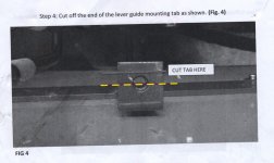
Step 4: cut off more of the mounting tab than shown, otherwise the tab will protrude through the 1st position lever slot on the new lever plate. I cut the tab off halfway through the threaded hole. The hole is no longer used or usable once the kit is installed, so it won't matter. I dabbed some automotive touchup paint on the cut edges afterwards.
Step 8: instructions refer to figure 7, but should instead refer to figure 8. Don't bother tightening the 90-degree o-ring boss fittings to the valve section yet, as you will later need to turn them slightly to get all the hoses to fit together. Due to the braided jacket over the hoses, and the large stainless steel crimp bands for the jacket, the hoses are unable to nest neatly as shown in the illustrations. There is also an interference issue with the detent valves (more on that below).
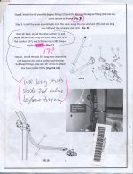
Step 10: if also installing 2nd or 3rd valves, this is the point where you'd instead use the longer studs supplied with those kits and stack all the valves at the same time (same image above). Because of limited clearance between the rear main case and the fender, the valve stack and studs need to be positioned in place and then the studs can be threaded into the manifold block. I found it helpful to put two temporary nuts on the outer end of the studs, tightened against each other, then use them to help thread the studs into the manifold block. When done, the temporary nuts can be undone and removed, and the permanent washer and nut threaded on. NOTE: I just noticed that instructions for the first valve kit say to torque studs to 11 ft-lbs, whereas instructions for the 2nd position kit (L7364) and float valve kit (L7354) spec 17 ft-lbs. I used 11 since I was following along the first set, but this should be clarified by Kubota and be consistent.
Step 12: connecting the valve manifold block inlet to the power beyond port on the front loader -- there will already be a hose connected to the loader's power beyond, supplying flow to the 3-point hitch. That hose must be removed first, and will need to be used later on.
Step 13: remove 3-point position stops from old lever plate and reinstall on new lever plate -- the original factory-installed lower "knob" stop has captive threads, and cannot be removed from the old lever plate without destroying the knob. A new knob assembly should be included with the kit, or can be ordered separately as part numbers: 04512-60060, 31351-18860, 37410-52610, TC402-36140 (total approx $7).
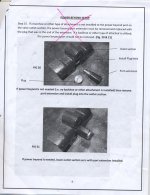
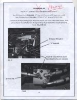
Step 15: calls for removing/plugging the power beyond port from the valve outlet section unless backhoe or other attachment is present. This port should not be removed/plugged under any circumstances, as it's needed to re-route power beyond flow to the tractor's built-in 3-point hitch even when there is no backhoe or other attachment present. So leave it attached. Take the hose removed in Step 12, and connect one end to the valve outlet power beyond port, and the other end to the hydraulic block under the floorboard (below brake pedals), using the same port the hose was formerly attached to. This process is somewhat illustrated in Figures 22 and 23 under the section "FOR BACKHOE USE", though it's required whether there's a backhoe or not. Step 15 also misses the requirement to install plugs on the end of the outlet sections.
Summary: I believe the errors in steps 12 and 15 came about because the person doing the test fit had access to an L model with backhoe already installed, and made assumptions about that. These steps overlook the basic fact that loader-only tractors route power beyond flow from the loader valve block to the 3-point hitch. When installing the rear remote valves, they are inserted into the power beyond loop after the loader and before the 3-point hitch. Thus, it's critically important to route power beyond flow from the rear remote outlet back to the hydraulic block under the floorboard, where it supplies the three-point hitch. Not doing this step, as the instructions suggest, would disable the 3-point hitch and potentially cause an undesirable/unsafe condition where the power beyond flow got blocked off and was unable to loop back to the reservoir.
Corrections - Part L7354 Float Valve Kit Instructions
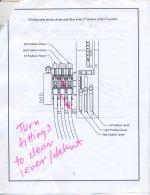
Illustrations on page 2 and in figure 3 on page 4 show 90-degree o-ring boss fittings aligned so that hoses run straight back. However, this arrangement will prevent the valve lever from pivoting fully forward into detent, as the rear linkage hits the lower of the two hoses (rearmost hose). The fittings should be turned about 35 degrees to the side, and hoses positioned so that the lever can move freely into detent. This correction applies with any detent valve, whether it's the float valve (L7354) or the standard detent valve (separate part/kit).
Corrections - Part L7334 1st Position Valve Kit Instructions (for tractor with front loader)
Step 4: cut off more of the mounting tab than shown, otherwise the tab will protrude through the 1st position lever slot on the new lever plate. I cut the tab off halfway through the threaded hole. The hole is no longer used or usable once the kit is installed, so it won't matter. I dabbed some automotive touchup paint on the cut edges afterwards.

Step 8: instructions refer to figure 7, but should instead refer to figure 8. Don't bother tightening the 90-degree o-ring boss fittings to the valve section yet, as you will later need to turn them slightly to get all the hoses to fit together. Due to the braided jacket over the hoses, and the large stainless steel crimp bands for the jacket, the hoses are unable to nest neatly as shown in the illustrations. There is also an interference issue with the detent valves (more on that below).

Step 10: if also installing 2nd or 3rd valves, this is the point where you'd instead use the longer studs supplied with those kits and stack all the valves at the same time (same image above). Because of limited clearance between the rear main case and the fender, the valve stack and studs need to be positioned in place and then the studs can be threaded into the manifold block. I found it helpful to put two temporary nuts on the outer end of the studs, tightened against each other, then use them to help thread the studs into the manifold block. When done, the temporary nuts can be undone and removed, and the permanent washer and nut threaded on. NOTE: I just noticed that instructions for the first valve kit say to torque studs to 11 ft-lbs, whereas instructions for the 2nd position kit (L7364) and float valve kit (L7354) spec 17 ft-lbs. I used 11 since I was following along the first set, but this should be clarified by Kubota and be consistent.
Step 12: connecting the valve manifold block inlet to the power beyond port on the front loader -- there will already be a hose connected to the loader's power beyond, supplying flow to the 3-point hitch. That hose must be removed first, and will need to be used later on.
Step 13: remove 3-point position stops from old lever plate and reinstall on new lever plate -- the original factory-installed lower "knob" stop has captive threads, and cannot be removed from the old lever plate without destroying the knob. A new knob assembly should be included with the kit, or can be ordered separately as part numbers: 04512-60060, 31351-18860, 37410-52610, TC402-36140 (total approx $7).
Step 15: calls for removing/plugging the power beyond port from the valve outlet section unless backhoe or other attachment is present. This port should not be removed/plugged under any circumstances, as it's needed to re-route power beyond flow to the tractor's built-in 3-point hitch even when there is no backhoe or other attachment present. So leave it attached. Take the hose removed in Step 12, and connect one end to the valve outlet power beyond port, and the other end to the hydraulic block under the floorboard (below brake pedals), using the same port the hose was formerly attached to. This process is somewhat illustrated in Figures 22 and 23 under the section "FOR BACKHOE USE", though it's required whether there's a backhoe or not. Step 15 also misses the requirement to install plugs on the end of the outlet sections.


Summary: I believe the errors in steps 12 and 15 came about because the person doing the test fit had access to an L model with backhoe already installed, and made assumptions about that. These steps overlook the basic fact that loader-only tractors route power beyond flow from the loader valve block to the 3-point hitch. When installing the rear remote valves, they are inserted into the power beyond loop after the loader and before the 3-point hitch. Thus, it's critically important to route power beyond flow from the rear remote outlet back to the hydraulic block under the floorboard, where it supplies the three-point hitch. Not doing this step, as the instructions suggest, would disable the 3-point hitch and potentially cause an undesirable/unsafe condition where the power beyond flow got blocked off and was unable to loop back to the reservoir.
Corrections - Part L7354 Float Valve Kit Instructions
Illustrations on page 2 and in figure 3 on page 4 show 90-degree o-ring boss fittings aligned so that hoses run straight back. However, this arrangement will prevent the valve lever from pivoting fully forward into detent, as the rear linkage hits the lower of the two hoses (rearmost hose). The fittings should be turned about 35 degrees to the side, and hoses positioned so that the lever can move freely into detent. This correction applies with any detent valve, whether it's the float valve (L7354) or the standard detent valve (separate part/kit).
