B21 Backhoe Thumb

   / B21 Backhoe Thumb #1  

downsizingnow48

Elite Member
Joined
Jul 29, 2013
Messages
2,749
Location
Sacramento, California
Tractor
Kubota B21
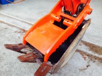
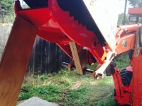
After 10 years I finally decided to install a hydraulic thumb on the B21. I was getting ready to make the thumb, and looked at Kubota parts diagrams to get some ideas. I learned that the BT751 backhoe and the BH77 backhoe use the same bucket pin. Meaning the buckets and also the mechanical thumb for the BH77 have to fit the BT751. The thumb cost $405 at the dealer, not a give-away, but not bad either considering steel prices and the work involved in making one from scratch.

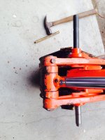
So today I did the easy part, installed the thumb. First picture shows the pin going in. I used a line-up pin with a tapered nose to get thumb, bucket, and stick in alignment, then chased that out with the hardened Kubota pin. It took about 3 minutes. The second picture shows the thumb installed.

It will be a while before I figure out exactly what the next step will be. Probably have to paint the old bucket, it didn't look that bad until I put the thumb on.

I am a bit concerned about the 25mm bucket/thumb pin, which is a Kubota factory item for the BH77, but looks a bit long and thin. The middle part of the pin is not supported (it is in a grease cavity). The bucket will work the same as ever, no reason to hold back on that, but I believe I might take it easy with the thumb. Pressing thumb and bucket hard together would have the effect of flexing the pin in the middle.
 

Attachments

  • t1.jpg
    t1.jpg
    404.9 KB · Views: 988
  • t2.jpg
    t2.jpg
    526.2 KB · Views: 2,084
   / B21 Backhoe Thumb #2  
I am a bit concerned about the 25mm bucket/thumb pin, which is a Kubota factory item for the BH77, but looks a
bit long and thin. The middle part of the pin is not supported (it is in a grease cavity).

You are right to be concerned. Based on my experience with about a dozen hoe attachments and 6 thumbs,
a shared pin of this type should be at least 30mm. 1.5" even better.

That and the greasing problem eliminated pin-sharing in my homemade thumb design.

BTW, I also had a B21 and they do operate at lower pressure (2000-2100psi), but I still think that
that design is problematic.
 
Last edited:
   / B21 Backhoe Thumb
  • Thread Starter
#3  
Thanks for the note. I'm glad to know someone else sees that as a weak design. A larger pin would be better for sure, I see the B26 has 1 1/4" pins in that location. I did a couple web searches for broken BH77 bucket/thumb pins, didn't find anything, but that doesn't mean much. As a preventive measure (better safe than sorry) I can set the work port relief low, I don't need much pressure for that thumb. On grease, that is also a good point. The BH77 thumb was designed as mechanical so not expected to rotate. My plan there is to drill/tap the thumb pin bosses for flush-fit grease fittings.
 
   / B21 Backhoe Thumb
  • Thread Starter
#4  
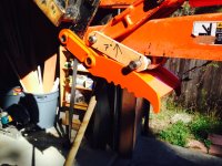
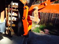
I decided to use a progressive linkage, to obtain more range of movement. It adds two more pins to share loads somewhat. This linkage also allows placement of the cylinder base further up the stick, reducing bending force.
 

Attachments

  • t5.jpg
    t5.jpg
    480.4 KB · Views: 723
  • t4.jpg
    t4.jpg
    485.2 KB · Views: 834
  • t3.jpg
    t3.jpg
    500.3 KB · Views: 980
   / B21 Backhoe Thumb #5  
A larger pin would be better for sure, I see the B26 has 1 1/4" pins in that
location.
They did do a number of improvements with the B26. The only non-improvements were the loss of the hood
armor and the higher price. Still a great machine.

When I speak of the problem with greasing a shared pin, I am referring to the fact that 3 or 4 places must get
grease, and this requires either 3/4 zerks on the bosses, or a single zerk on the pin's end with 3/4 holes. You
need only 3 places to grease if the pin is locked to the bucket bosses, which is usually the case.

A mechanical thumb setup does not accommodate greasing of the dipper stick pivot, either, which has
to be upgraded for hyd.

Since you are planning a multi-link system, it is good that you are doing some wood mockups. I did
that first with my articulating mech thumb.

I posted a thread about making a hyd thumb here:
http://www.tractorbynet.com/forums/...ustom-hydraulic-backhoe-thumb.html?highlight=

When you complete your design and fab, show it off here. I always like to see what folks come up with.
 
   / B21 Backhoe Thumb
  • Thread Starter
#7  
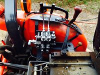
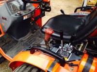
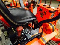
Last weekend I installed the control valve. Rather than have one valve dedicated to the thumb, I decided to install two valves, in a position where they can be used for other things as well.

The first photo shows the valve installed. It fits (barely) in the space between the left fender and the seat.

The second photo shows the valve in relation to the seat, forward facing. Both levers are easily to hand on the left, behind the transmission selector lever.

The third photo shows the valve in relation to the seat, backward (backhoe) facing. Both levers are still easily to hand, now on the right. It took a while to get the position figured out.

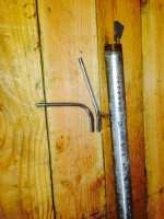
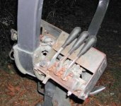
The fourth photo shows valve levers before and after bending, using a piece of pipe. The levers as supplied were not suited to this installation. So I bent them 90 degrees up and about 15 degrees to each side. This provides for easy operation.

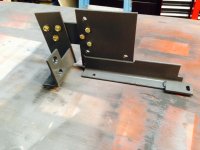
The fifth photo show the fabricated main bracket, which carries the valve and also the quick couplers leading back to the thumb. It is a bit complicated because it bolts to the forward fender mount, the middle fender mount, and the ROPS mount, at different angles and elevations. It holds the heavy valve solidly in the correct position with no trace of movement.
 

Attachments

  • T6.jpg
    T6.jpg
    525.8 KB · Views: 729
  • T7.jpg
    T7.jpg
    546.2 KB · Views: 688
  • T8.jpg
    T8.jpg
    553.9 KB · Views: 1,434
  • T9.jpg
    T9.jpg
    460.1 KB · Views: 393
  • T10.jpg
    T10.jpg
    424.9 KB · Views: 497
   / B21 Backhoe Thumb #8  
It fits (barely) in the space between the left fender and the seat.

Wow, that's a tight fit. Do the levers clear the seat?

I guess that is why the OEM AUX valves from Kubota (actually made by Gannon for Kub) are
mounted to the FOPS. The photo shows the triple valve.
 

Attachments

  • AUX_valves.jpg
    AUX_valves.jpg
    69.7 KB · Views: 470
   / B21 Backhoe Thumb
  • Thread Starter
#9  
There isn't any room to spare, for sure! But it all works OK. The levers, bent to the correct angle, clear the fender on push and the seat on pull. The seat rotates freely, and it has full travel on the slide adjustment. The fly in the ointment was the bulky inertial reel of the seat belt, which occupied about 100 cubic inches of space right in the way of everything. I'm still thinking about how to re-mount the seat belt, or maybe replace the stock item with a more compact alternative. It can be done one way or the other, I just haven't thought it through yet. On valve location, I considered the FOPS. I also looked at the factory setup, which is pretty nice. In the end I decided in favor of a valve location that would be equally accessible facing forwards or backwards.
 
   / B21 Backhoe Thumb
  • Thread Starter
#10  
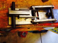
The photo shows the progressive linkage (yoke, links, shafts, bushings). After experimenting with the wooden mockup to test pivot point lengths from 6" to 8", I decided on 6.75" center to center. This is the final test assembly before welding up the yoke. The links are made of 3/4" x 2" mild steel bar, with 1.125" bronze bushings. The links don't have to be that heavy but that was the easiest way to get decent size (3/4") bearing surfaces for the shafts. The yoke is made of 3/16" mild steel rectangular tubing (1 piece 1.5" x 2.5", 1 piece 2" x 3") The tubing is sized to fit the thumb boss on one side (1.5"), and the cylinder rod end on the other (2.25"). The bushings for the yoke are chrome-moly tube, 1" ID x 1.5" OD. At the cylinder rod end there are two 1" bushings, and at the thumb boss end there is one 1.5" bushing. 6mm holes are drilled where needed for flush fit drive-in type grease fittings.
 

Attachments

  • T11.jpg
    T11.jpg
    487.3 KB · Views: 613
 
Top