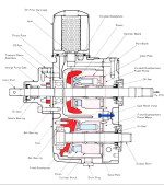
Apologies for long post.
I have replaced the HST input shaft with the stripped spline so I thought I'd give an update on things I learned along the way in case the information is useful to anyone else.
I've split the tractor, removed the HST, replaced the input shaft, bearing and seals plus a few other worn parts I found along the way.
The tractor now goes well. Here's some tips for anyone else who might do the same.
This writeup applies to tractors with Type 2 HST. I think the Type 1 HST shaft replacement will be the same process but can't guarantee that. See comments at the end about finding the right parts.
I think the job is quite achievable for a diy person who has some good mechanical skills and a good selection of tools.
The first challenge is splitting the tractor. This might seem a bit daunting at first but splitting and re-joining the tractor actually isn't too difficult.
I recommend you download the workshop manual and read the section on splitting the tractor before you start. I'm not going to repeat whats in the manual just some pointers.
The file for the manual is called B7100HST_WSM_complete.pdf and is found at
Index of Kubotabooks/Tractor Owners Manuals/
Note. Do not follow the WSM instructions for disassembling the HST because you don't have to strip the HST right down to replace the input shaft.
For me the fiddliest and time consuming part of splitting the tractor is removing and reinstalling the hydraulic pipes. I found it invaluable to take some cellphone pics of the pipe routing beforehand to help with the reassembly. Many of the banjo bolts are sealed with copper washers which often don't reseal so I replaced them with bonded washers (also known as Dowty washers). They are cheap and I have never had one leak.
When you take the filter off the top of the HST you also have to remove the threaded bit the filter screws into. After removing it I wiped the surfaces clean with thinners and covered the filter opening with plastic tape to keep muck out. I also plugged every hydraulic opening with lint free rag or plastic tape.
To roll the tractor apart I used 2 trolley jacks and a car stand. Place the stand under the towbar at the rear to stop the rear half tipping backwards. I put a small home handyman trolley jack under the front PTO housing that protrudes under the Range Transmission and jacked it up just enough to take a bit of weight, but not lifting anything off the ground. Chock the rear wheels firmly so they cannot move forward or backwards. I then put a larger workshop trolley jack just behind the clutch housing. The jack handle protruded out under the front axle, so the jack was in line with the tractor wheels. Make sure this jack has well lubricated wheels, and that there is no small stones etc. on the ground that will stop the jack wheels from rolling freely. I laid a sheet of plywood under the jack. Once again, take a little weight on this jack, but don稚 jack the tractor up.
Cut 2 wooden wedges and tap them in between the front axle and tractor frame. The front axle pivots under the frame, so if you don稚 put these wedges in the front frame and engine will flop over when you separate the tractor. I know this because it happened to me. That was my "Oh Bother!" moment (or similar words) because I was on my own, and stuck there holding it upright as I feared it would roll off the jack.
Once you have disconnected everything as per the workshop manual it is actually very easy to roll the front half of the tractor away from the rear. Before you split it, check youv?e done the following:
- Disconnect the linkage between the foot pedal and HST inside the pressed steel housing.
- Remove the spring that sticks out of the top of the same housing. Im talking about the spring that returns the pedal/HST to the neutral position.
- Knock out the roll pin in the driveshaft coupling to HST input shaft, and the roll pin in the U joint for the front wheel drive shaft.
Remove the HST from the tractor as per the workshop manual. The gasket made mine stick together. Pry it apart evenly top and bottom.
Input Shaft replacement
As I said, you do not have to disassemble the entire HST to replace the input shaft.
Here are the steps to remove the input shaft, but first set up a spotlessly clean work area. You must not get any contamination into the HST. If the system will allow I will post some photos of the following steps.
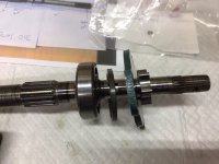
1. Remove the circlip, gear, bearing and 2nd circlip at the rear of the input shaft.
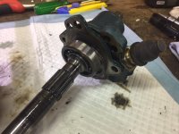
2. Undo the 3 hex head cap screws that hold the charge pump onto the HST. The charge pump is the housing thing that the input shaft goes into on the front of the HST.
3. With a plastic mallet carefully tap the rear of the input shaft and the input shaft with charge pump and a bearing will come out the front of the HST.
4. As you do the next step to take the shaft out of the charge pump I recommend you take pictures as you get it part way out, then again when fully out. You should work over a flat, clean work area as a keyway can fall out.
5. Make sure there are no burs or protrusions on the front of the input shaft.
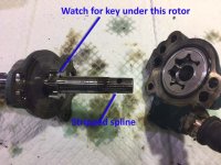
6. You might need two people to do this step. Hold the charge pump housing with the shaft horizontal (very important) and tap the front of the input shaft. The shaft, bearing, spacer, plate, pump rotor, key and maybe some other parts off the pump will come out. If you are careful as you pull it apart you will see how the parts all go together. Hopefully you will not end up with a pile of bits on the bench/floor.
7. You can now slide most of the bits off the shaft. Watch out for the half moon key under the pump rotor.
Also watch out that the other bits inside the pump don't fall out. I tied and taped groups of parts together in the order they came off, then sealed them into clean ziplock plastic bags.
8. I replaced the input shaft and the bearing. The bearing is a standard 6304 (no seals) that presses onto the shaft easily and is also located in place with a circlip.
9. I also replaced the oil seal at the front of the charge pump and the oil seal at the rear of the HST. They are standard size seals. I didn't replace the o-rings where the charge pump joins the HST.
Reassembly tips
10. Assembly is the reverse but the first trick is to get the shaft and all its bits back into the charge pump without the key falling out of the pump rotor. It took me about 5 tries to get it right.
Most important that you do not force anything together. It is all precision machined and should slide in by hand.
11. The second trick is to get the charge pump and shaft back into the HST without the shaft/pump assembly sliding apart and bits falling out especially the key.
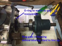
12. When you get the shaft back into the HST there is two things to watch for
a/ the spacer next to the 6304 bearing must be lined up with the hole the bearing went into. It easily gets out of line
b/ the large diameter o-ring between the HST and charge pump housing are easily knocked out of place.
Finding the correct shaft? was a challenge.
Be careful about ordering an input shaft online. The part number from the catalogue was not the right size part for my tractor. Here痴 what I mean.
According to the workshop manual my tractor serial number should have had a type 1 HST which the online parts catalogues say should use a shaft part number 66415-39310
But according to the parts manual from Kubotabbooks.com my tractor serial number should have had a Type 2 transmission, which should use a shaft part number 66415-39315
Turned out my tractor had Type 2 - The TYPE l l cast into the top of the housing was a give-away.
Apparently Type 1 and 2 have different length input shafts. My shaft was approx. 310mm (12.2in) long
However the local Kubota dealer told me the shaft part number listed for a type 2 and was not the same as mine. After a lot of investigation by the Kubota dealer we got the following part that matched mine.
Kubota part number 66204-84310
Kubota description SHAFT TRAC HST
This cost a bit over $330NZD plus GST (about $220USD).
I did consider getting my shaft re-splined, but it was estimated at $200NZD, so in my opinion not worth the risk/effort
Hopefully Pics are attached here
