Repairing MF35 Utility Hydraulics

   / Repairing MF35 Utility Hydraulics #1  

shaeff

Veteran Member
Joined
Oct 27, 2015
Messages
1,048
Location
Hudson Valley, NY
Tractor
MF Utility 35 Gasser, JLG LJ500
Some of you may remember my thread from a few months back:
http://www.tractorbynet.com/forums/...c-vintage/347197-early-60s-mf-35-utility.html

Well, life got in the way for a while and the tractor was on the back burner for a few months while I sorted out other issues. To sum up my issue from the last thread (which is way long at this point), I bought a MF35 Utility, got it all up and running except the rear hydraulics did not function. I came to the conclusion that the lift cylinder studs snapped off of the lift cover assembly. I finally got around to opening up the rear of the tractor on Saturday, and that's exactly what happened. I'm not sure whether it's due to water ingress, or the previous owner lifting something that was way to heavy and possibly bouncing it over a bump. The fact remains that the lift cylinder is indeed snapped off, all four studs. It otherwise seems to be in good condition.

I have the factory AGCO manuals, but one of the exploded diagrams is still leaving me with a question concerning the hydraulic pump. Considering how easy it was to remove the lift cover, I'm tempted to fix the lift cylinder and put it back together to see if it all functions, but wanted some opinions first.

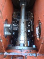
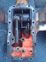
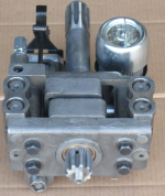
Third picture below shows the innards of the tractor as seen from the rear. The lift cylinder was sitting on top of the main drive coupler, and the rock shaft was hanging down. In the upper right corner, all the way down in front of the hydraulic pump, I found a very long spring. It looks as long as the springs used for the lift/draft controls. I know there is a spring in the hydraulic pump down in that area as shown in the second picture I got from Google. This spring I found is easily 8-10" long. Is it likely that it came from the lower left side of the hydraulic pump picture?

I'll have to try and drill out the four broken studs, as the lift cylinder appears otherwise undamaged. I'd like to reuse it if possible. Aside from the usual o-rings here and there, is there anything else I should replace inside? Can I fill this thing with some diesel (to continue to flush the system) and run it with the lift cover off to see if the pump works? Without the stand pipe bolted in, I'm betting it would make a huge mess, right?

Thanks, all!
 

Attachments

  • cover.JPG
    cover.JPG
    719.3 KB · Views: 11,086
  • mf 35 hydro pump.png
    mf 35 hydro pump.png
    823.3 KB · Views: 5,633
  • trans.JPG
    trans.JPG
    459.4 KB · Views: 10,223
   / Repairing MF35 Utility Hydraulics #2  
Some of you may remember my thread from a few months back:
http://www.tractorbynet.com/forums/...c-vintage/347197-early-60s-mf-35-utility.html

Well, life got in the way for a while and the tractor was on the back burner for a few months while I sorted out other issues. To sum up my issue from the last thread (which is way long at this point), I bought a MF35 Utility, got it all up and running except the rear hydraulics did not function. I came to the conclusion that the lift cylinder studs snapped off of the lift cover assembly. I finally got around to opening up the rear of the tractor on Saturday, and that's exactly what happened. I'm not sure whether it's due to water ingress, or the previous owner lifting something that was way to heavy and possibly bouncing it over a bump. The fact remains that the lift cylinder is indeed snapped off, all four studs. It otherwise seems to be in good condition.

I have the factory AGCO manuals, but one of the exploded diagrams is still leaving me with a question concerning the hydraulic pump. Considering how easy it was to remove the lift cover, I'm tempted to fix the lift cylinder and put it back together to see if it all functions, but wanted some opinions first.

Third picture below shows the innards of the tractor as seen from the rear. The lift cylinder was sitting on top of the main drive coupler, and the rock shaft was hanging down. In the upper right corner, all the way down in front of the hydraulic pump, I found a very long spring. It looks as long as the springs used for the lift/draft controls. I know there is a spring in the hydraulic pump down in that area as shown in the second picture I got from Google. This spring I found is easily 8-10" long. Is it likely that it came from the lower left side of the hydraulic pump picture?

I'll have to try and drill out the four broken studs, as the lift cylinder appears otherwise undamaged. I'd like to reuse it if possible. Aside from the usual o-rings here and there, is there anything else I should replace inside? Can I fill this thing with some diesel (to continue to flush the system) and run it with the lift cover off to see if the pump works? Without the stand pipe bolted in, I'm betting it would make a huge mess, right?

Thanks, all!
I'm more familiar with the TO/TE-20, -30, which has a different hydraulic control system. However I don't see that anything is damaged from whatever broke the lift cylinder attach bolts. Before you attempt to use the same lift cylinder, check the lift cover mating surfaces for flatness to make sure the lift cylinder was not distorted.

Attempting to run diesel in the system with the lift cover off will give you a geyser of diesel out of the standpipe. I'd build a defector (slide a rubber hose over it and point the end down into the sump) over the standpipe to pump the fluid back into the hydraulic compartment. It will tell you that the pump will pump with no restriction on it and that's not much info. I'd just try to turn the pump via the pro shaft by hand or maybe with a pipe wrench to see if there is anything mechanically interfering with it. If there is, drop the pump. If not, reassemble and test with fresh fluid after you have it buttoned up. You'll get meaningful information with the regular restrictions in the hydraulic circuit.

I'm pretty sure if the pump needs rebuilding it can be dropped without removing the lift cover. But check your shop manual to be sure.

As far as that spring, look in the parts manual to see where it goes. I don't think it's on the pump. I think it is under the lift cover where the control levers are attached. maybe someone with more MF 35 experience can be more helpful.
 
   / Repairing MF35 Utility Hydraulics #3  
I've run the engine at idle with the lift cover off, and moving the pump control lever back and forth you should see the oil flow off and on out the standpipe hole. Pump comes out the top on the 35, 50, and 65 models, not out the bottom like 20 and 30. MAKE sure when replacing the lift cover the levers are in FRONT of the roller, I've used the dipstick through the lower side plate hole to hold the lever back.
 
   / Repairing MF35 Utility Hydraulics
  • Thread Starter
#4  
I'm more familiar with the TO/TE-20, -30, which has a different hydraulic control system. However I don't see that anything is damaged from whatever broke the lift cylinder attach bolts. Before you attempt to use the same lift cylinder, check the lift cover mating surfaces for flatness to make sure the lift cylinder was not distorted.

Attempting to run diesel in the system with the lift cover off will give you a geyser of diesel out of the standpipe. I'd build a defector (slide a rubber hose over it and point the end down into the sump) over the standpipe to pump the fluid back into the hydraulic compartment. It will tell you that the pump will pump with no restriction on it and that's not much info. I'd just try to turn the pump via the pro shaft by hand or maybe with a pipe wrench to see if there is anything mechanically interfering with it. If there is, drop the pump. If not, reassemble and test with fresh fluid after you have it buttoned up. You'll get meaningful information with the regular restrictions in the hydraulic circuit.

I'm pretty sure if the pump needs rebuilding it can be dropped without removing the lift cover. But check your shop manual to be sure.

As far as that spring, look in the parts manual to see where it goes. I don't think it's on the pump. I think it is under the lift cover where the control levers are attached. maybe someone with more MF 35 experience can be more helpful.
I have a friend who has a mechanic's straight edge, so I'll use that to check the lift cover. When I emptied the case of oil right after I got the tractor, there was a little oil, and mostly water. I'm fairly certain that the case froze and broke the lift cylinder off. Luckily just those four studs, so as long as I can drill them out, hopefully I should be good. My main concern is with that large spring I found in the bottom of the case. Looks to be the size of the hydraulic lift/draft control springs, but it was broken in half and in the front right of the case near the lift pump as you look at it from the back. I need to make sure that spring didn't come from the lift pump. Maybe I'll try filling the case a bit and making a deflector just in case my RPM are a touch high when it fires. I know there's nothing interfering with the pump, as the PTO works fine, and I've driven the tractor (before I figured out what went wrong in the case) There were no odd noises or anything.

I don't see any way of getting the hydraulic lift pump out without pulling the top cover again, nor did I see any other method in the AGCO manual. That's why I'm considering pulling the pump now while the lift cover is off, replace o-rings and whatever is worn, refurbish the adjustments on the lift cover, then I know everything back there will last me another fifty years.

I did look in the parts manual to see where that large broken spring goes, but since I'm 100% unfamiliar with the pump I can't say for sure. It appears to be the size of the lift/draft lever springs, but neither of those are missing (maybe replaced and the old one fell in the bottom?) and I don't want to risk putting it back together then have to pull it all back apart.

I've run the engine at idle with the lift cover off, and moving the pump control lever back and forth you should see the oil flow off and on out the standpipe hole. Pump comes out the top on the 35, 50, and 65 models, not out the bottom like 20 and 30. MAKE sure when replacing the lift cover the levers are in FRONT of the roller, I've used the dipstick through the lower side plate hole to hold the lever back.

Yep, I see where the stand pipe connects to the pump, I just wanted to be sure it wouldn't force fluid out like crazy. As for your last statement, I've read that a few times. I just read a thread on another forum where a guy fixed his lift cover adjustments and lift cylinder, started the tractor, and the lift arms when all the way up, didn't stop, and snapped the rear of the tractor nearly in half! That would be terrible, so I may order the vintage tractor engineer DVD regarding the hydro pump overhaul and draft/lift adjustments. I want to make sure I've got it 100% correct before starting it. Maybe I'll leave the lift lever in the down position, and crank it over with the coil disconnected to make sure that the lift arms don't do anything funky.

Thanks for the suggestions guys.

Edit: just for kicks, I looked on eBay for new hydraulic pump, found one sold by a fella named hamiltonbobscubs that's supposedly new for about $120. If I were to go that route, just for peace of mind, I'd replace the relief valve with a new factory unit to ensure it doesn't over pressure my system. The only reason I'm asking, is that a rebuild kit costs about $170 from various sources. Thoughts? Are these pumps any good?

Here's a link: New Hydraulic Lift Pump Fits Massey Ferguson MF to 35 50 65 MF35 TO35 MF50 MF65 | eBay

vs rebuild kit:
Ferguson Hydraulic Pump Repair Kit for Ferguson 35,65,135,TO35,150,165,175,202,2135,302,304,50,765 - S.40843
 
   / Repairing MF35 Utility Hydraulics #5  
On my friend's 35, I had the gearbox off the rear casing to renew gearbox bearings and seals a couple of years ago. I believe the pump from memory would have been easily removed at this point as well - only a front PTO shaft to remove, although it's a snack to remove the top cover in comparison to splitting the casings behind the gearbox. BTW, you may need to remove your PTO output shaft in order to remove the hyd pump with PTO front shaft. I can't remember the finer points with any accuracy, but looking at your 3rd pic, it may be difficult to get the pump upwards past the gearbox-to-diff driveshaft.
 
   / Repairing MF35 Utility Hydraulics
  • Thread Starter
#6  
Yep, according to the manual, the main driveshaft has to come out (easy, pull cotter key/slip yoke), and the PTO shaft as well, which is also pretty simple- pull the bolts off the rear PTO housing and slide it out. This coming Saturday I should have the pump out, then I'll start making a parts list.
 
   / Repairing MF35 Utility Hydraulics #7  
Great stuff! You have an advantage - a manual to consult. I forgot about the splined sleeves! They were intended to fail in the event of inordinate shock loads before anything major was damaged, and be renewed easily. Have never seen one broken though - they must be pretty tough, like everything else! Nothing scary there ... just be careful and attentive to detail, a reasonable standard of cleanliness and specs & settings. Give it your best shot. :thumbsup:
 
   / Repairing MF35 Utility Hydraulics
  • Thread Starter
#8  
Well, I gave it a shot today. Got the sheer collar out in about 40 seconds. I cannot, however, get the PTO shaft out. I removed the three bolts for the retaining ring, I pulled the large diameter seal retainer with no issues.

I had a screwdriver through the hole in the PTO shaft and pried against the rear of the tractor with huge pry bars, still no luck. The shaft spins freely, but I'm guessing that the water in the case seized the shaft inside the inner bearing race. Suggestions? Other than this setback, the hydraulic pump is ready to come out!
 
   / Repairing MF35 Utility Hydraulics #9  
The bearing is seized into the transmission casing. You need a slide hammer to "shock" it into moving. Don't forget there's a serious amount of oil there! Tapping it inwards a little may also achieve this. I'm pretty sure they are all the same - two pry-bars or some sort of slide-hammer on a strong bolt through the hole in the shaft might be needed to move it outwards. The bearing has from memory a snap ring/circlip before it on the PTO output shaft and this shaft should come straight out the back with the bearing on it. Renew the seal, O-ring and bearing (they are very cheap) and grease the outside of the bearing and the seal lip on reassembly. I would also strongly recommend fitting the protective cap available for covering the PTO shaft and seal area.
 
   / Repairing MF35 Utility Hydraulics
  • Thread Starter
#10  
The bearing is seized into the transmission casing. You need a slide hammer to "shock" it into moving. Don't forget there's a serious amount of oil there! Tapping it inwards a little may also achieve this. I'm pretty sure they are all the same - two pry-bars or some sort of slide-hammer on a strong bolt through the hole in the shaft might be needed to move it outwards. The bearing has from memory a snap ring/circlip before it on the PTO output shaft and this shaft should come straight out the back with the bearing on it. Renew the seal, O-ring and bearing (they are very cheap) and grease the outside of the bearing and the seal lip on reassembly. I would also strongly recommend fitting the protective cap available for covering the PTO shaft and seal area.

Ah nuts, the forum glitched and I lost my lengthy response. I'm out of time, so I'll leave the abridged version:

I tried a slide hammer quickly but had used a piece of chain to connect it. I'm lost too much striking force through the chain, I need to figure something more rigid, maybe bend something through the PTO shaft and just cut it off when I'm done. I'll figure something out. I tried tapping it inwards as well, but didn't want to destroy the bearings. If I have to, then so be it, it'll give me a reason to grab a nice hydraulic press. :)

I've got a parts list going so I can make one large order for everything I'll need. If i can save the bearing I'd like to, as it's still smooth as silk with literally no play in it that I can feel at all. I'll also grab one of those PTO caps, that'll help keep out some of the debris when it's not in use.

Thanks, Patrick!
 
 
Top