Auxiliary Hydraulics for GC2400

   / Auxiliary Hydraulics for GC2400 #1  

porky69

Silver Member
Joined
Jun 28, 2007
Messages
105
Location
Coaldale, Alberta, Canada
Tractor
2009 Massey Ferguson GC2400
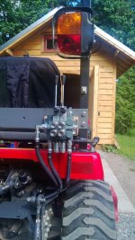
If I wanted to add an extra hydraulic circuit or two ;) to my GC2400 how would be the best?

I looked at a GC2410 on a dealer lot figuring that the backhoe hook up would be about the same as auxiliary spools but it was cold, wet and snowy :eek: around the tractor so I couldn't get a good look.

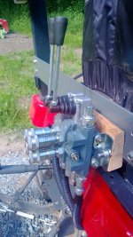
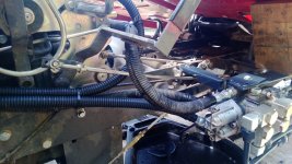
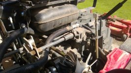
I seen that one hose comes from the loader valve block (I assume this would be a pressure line) but couldn't see which port it hooks to (I see there are 3 rubber hoses coming out of the valve block on my GC2400). Does anyone know which one it is?

I would assume it hooks to a power beyond port, which if I understand hydraulics right would also be going to the 3pt hitch controls. If it is going to the 3pt hitch could I just put a tee inline and have the original hose go to the 3pt and a second line to my auxiliary valves?

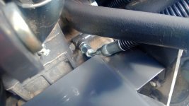
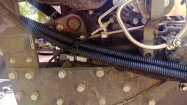
I did see that the other hose goes to a fitting on the right rear side of the differential housing, I found this one on my tractor and see there is already a port there with a plug in it. I would assume this is the return line.

Am I on the right track? Any help would be greatly appreciated.
 
   / Auxiliary Hydraulics for GC2400 #2  
Looking at adding a set of quick connects to run a cylinder or something out the back of tractor. Has anyone added extra hydraulics to their GCs?
 
   / Auxiliary Hydraulics for GC2400 #3  
I just got done adding a valve and a set of rear remotes on mine. I'm planning on running top and tilt cylinders with them.
I hooked into the factory-installed FEL valve on mine. From your signature it looks like you have the same setup so you could do the same thing.
According to the service manual this is also how the backhoe hydraulics are hooked up.
The base plate of the loader valve has three ports. The service manual doesn't have information on what they are so I experimented and found, from top to bottom: Pressure, Tank, Power Beyond.

I needed three new hoses:
1 - from PB port of FEL valve to P port of aux valve
2 - from PB port of aux valve to P port of 3PH
3 - from T port of aux valve to tank
#1 and #2 replace the factory hose that runs from the FEL PB port to the P port of the 3 pt valve.

All hose fittings need to be BSPP, the hoses should be 3/8" in size. I found that not all hydraulics stores stock BSPP fittings so it might be worth giving them a ring first.
The hose that runs to tank (#3) can be connected to the tank fitting at the rear, roughly to the right of the fluid level glass. There is a plug below the right lift arm that you take out and that is where you can connect the hose. For that the hose needs to have a male end on a 45 deg angle. All other ends are female.
I ran hoses 1 & 2 between frame and right wheel along the FEL tank line. I believe this is where the lines run on backhoe equipped machines as well -- I don't see room anywhere else.
When shopping for a valve try to match the GPM figure of the tractor (6gpm). In other words, get a small valve. Otherwise, it'll be hard to find room for it and it'll require lots of adapter fittings. I got an 11gpm valve (Bucher HDS-11) and that's about the biggest I would use. Also, the valve must be open center and have a PB port.
I mounted the valve behind the seat so that the cylinder ports are pointing backwards and I screwed the QDs directly into the valve with only an adapter (as opposed to routing the QDs to their own bracket). I will have to see how that holds up in the long run.

If you are interested I can post a few pics.
 
Last edited:
   / Auxiliary Hydraulics for GC2400 #4  
Thanks for the info, would love to see pictures.:thumbsup:
 
   / Auxiliary Hydraulics for GC2400 #5  
I'd like to see pics also please.
 
   / Auxiliary Hydraulics for GC2400 #6  
Here you go :)

The first two pictures show what the valve looks like and where I mounted it. Note that I haven't made the final bracket yet, right now it just sits on a block of wood mounted to a crossbar. You can see how the 2 pairs of QDs are screwed right into the valve. The P port is on the right, the PB port on the upper left (with the 90 deg fitting) and the tank port is the one on the left.

The third pic shows how the aux valve is connected to the tank fitting.

Fourth pic: Pressure lines to and from aux valve are routed between frame and right wheel, alongside existing tank line.

Fifth pic shows the new lines (the clean ones): The bottom one from FEL valve PB port to aux valve P port. the top one from aux valve PB port to 3PH P port.

Last picture shows the old line from FEL valve PB port to 3PH valve P port. It is the line in the back, halfway under the tank & held up by a ziptie. This line got replaced by the two in the previous picture.
 

Attachments

  • WP_20130618_005.jpg
    WP_20130618_005.jpg
    281.1 KB · Views: 3,691
  • WP_20130618_002.jpg
    WP_20130618_002.jpg
    288.5 KB · Views: 4,282
  • WP_20130618_001.jpg
    WP_20130618_001.jpg
    197.4 KB · Views: 1,037
  • WP_20130605_002.jpg
    WP_20130605_002.jpg
    290.4 KB · Views: 1,162
  • WP_20130605_001.jpg
    WP_20130605_001.jpg
    311.6 KB · Views: 1,239
  • WP_20130603_001.jpg
    WP_20130603_001.jpg
    306.9 KB · Views: 1,341
   / Auxiliary Hydraulics for GC2400 #7  
Thank you for the pictures, great job by the way.:thumbsup:
 
   / Auxiliary Hydraulics for GC2400 #8  
Great job maxa. Thank you for the pictures and description.
 
Last edited:
   / Auxiliary Hydraulics for GC2400 #10  
Thanks for posting pics.
 
 
Top