MF Front Loader Hydraulic layout

   / MF Front Loader Hydraulic layout #1  

congo181

Member
Joined
Sep 24, 2012
Messages
47
Location
Maidstone, Kent
Tractor
Massey Ferguson 35, 1964
Hi all.
I'm refurbishing a very sad and rusty front loader for my MF35 that I dragged out of a field in the UK.

I'm about to look at the hydraulics and have wondered were the pipes and control lever are normally located for this tractor.
It's a single acting system (push only on the rams although they do have connectors both ends).

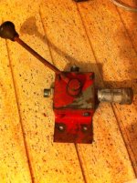
See below for a photo of the control lever which I got with the loader. It seems to have a quick connector on one side (for something else?). The other side went to the two ram pipes via a T, and the top appears to be the inlet pipe.

So, where do these pipes get routed on a MF35, and where does the control get mounted?
(My tractor has a banjo to the front left of the seat, with a pipe to the rear for a tipper etc, and a valve with a outlet left and right, but I cant see a screw valve being any good for a loader?)

Cheers,
Jim
 

Attachments

  • Loader Control.JPG
    Loader Control.JPG
    242.4 KB · Views: 608
   / MF Front Loader Hydraulic layout #2  
G'day congo181.
Take some pictures of the tractor and loader and let me see what you have ,and we will go from there.
Regards.
Hutch.
 
   / MF Front Loader Hydraulic layout
  • Thread Starter
#3  
Hi again Hutch.

Well its quite difficult to take useful photos as the loader is in parts being refurbished by me at the moment. I've got quite far, and am pleased with the results up to now.
I have added a picture of the as-yet untouched forks for interest and to see what it was like before I started work on it all.
Forks 1.JPG Forks 2.JPG

I have laid out the parts next to the tractor so you can see where I am coming from.
I have positioned the uprights lateraly where they mount onto a cross beam on the underside of the tractor (not yet fitted).

Layout.JPG Location.JPG Main Parts.JPG Hose T.JPG

Some of my observations.
The T on the hoses has a distinct angle on the input side. I am guessing that it makes sense that the input hose angles upwards when mounted, leading me to believe that the control would have been to the RHS of the tractor.
The rams are single acting. The top inputs are blanked off, and there is only one set of hoses. I assume that when the control is shut off, then rams would drop under the weight of the load/forks, but where does the oil go?
The dead side of the control has a quick connector on it (See original post). Can we safely assume that this was just for some other attachment(s) in a previous life?

So does any of this help with my original question: whats the normal routing of the hoses and control lever, and how does the control connect to the hydro output on the tractor.

Cheers, Jim
 
   / MF Front Loader Hydraulic layout #4  
G'day Jim.
The valve in the photograph is not familiar to me but if you had an air compressor you would be able to work out the flow path of the valve does the valve have two holes drilled through the body same centre to centre measurements as the hydraulic blanking plate on the front right hand side of the hydraulic lift cover if so it will bolt on in place of the blanking plate, Caution Do not remove the plate unless the three point linkage is at its lowered position ,I suspect that the quick connect is for a hydraulic tipping trailer!!

You are in the UK. So if you contact your local Bareco, Sparex or Bepco agent they will know what you want.
Ask for a beecraft type selector valve,this is a push pull type hydraulic valve which replaces the blanking plate mentioned above,connect the loader hoses directly the the valve .

With the valve button pushed IN this will give you three point linkage control .

with the valve button PULLED OUT this will give you hydraulic supply to the loader it will be controlled by the DRAFT lever the one nearest the mudguard just play around with it and you will work out how it works.
The position control lever will have to be in the forward Fast position this will give maximum hydraulic pressure when you are lifting something .

The lift rams ,the ram hydraulic connections should be installed with the hydraulic connections facing up ,not as shown in the photographs.

Note: If and when using the loader it will be found neccessary to ad a counter Weight to the three point linkage, We have used in the past a grader blade or such like implement or a 45 gallon drum with a hole punched through just above centre and filled with gravel or the like ,attach to the three point linkage.
This should be enough information to get you on the right track.

Be carefull and keep the littlies well away from the area of work.

Regards.
Hutch.
 
   / MF Front Loader Hydraulic layout
  • Thread Starter
#5  
Hi Hutch.
This valve isnt designed to go onto the cover plate as per your description - it just bolts onto something and looks to be just a 2 way selector. Probably no good to me in this application.
I understand about the valve onto the top cover plate. Does this look to be the right one?
There are 2 options, both with and without a return line. So with these valves, the return oil when lowereing the loader will be controlled by the draft too?

I have read somewhere that it is possible to also control the 3point at the same time, to allow the lifting of a counterweight. Have you seen this situation? Would it work, selecting the 3 point, lifting the balance, and then selectting the loader? Would the 3point remain where it was?

On my tractor currently, to the left of the seat on the opposite side to the cover plate, there is a banjo, with a pipe to the rear for a tipper. On top of this is a valve with two ports and a screw valve which opens both ports. Is this just an auxilliary feed?

Thanks so much for your input. I spent all day grinding and red-oxiding one side of the front forks, so its good to know all that work is still probably worth it.
Re little ones, you mean she should play with the grinder?
 
   / MF Front Loader Hydraulic layout #6  
g'day congo181.
Yes that is the valve you want ,when it is connected operate the valve so that ist gives you three point linkage control and lift your chosen counterweight to the height you want and then change the valve and set the Position control lever in the fast ,forward position and control the loader with the draft lever.

The two loader ram hoses go into the tee piece from there to the valve ,I am not sure which port is the supply so you will have to carefully operate the selector valve and see which one the oil comes out of do this with the engine stop pulled out and just crank the engine over with the draft lever all the way back this will minimize the oil loss and the big puddle on the shed floor, only Joking.
The oil travels both ways through the valve that is operate the draft lever to the up position to supply pressure and down to dump the oil to sump.

The littlie should only use the grinder if properly trained and is using all the neccessary PPE!!!.
Happy Days.
Hutch.
 
   / MF Front Loader Hydraulic layout
  • Thread Starter
#7  
Hutch.

Fantastic. Thanks so much. I am almost ready to start spraying the parts red. Keep your fingers crossed that the rams don't leak toooo much :)
Guess I better order one of the valves. Did you see the two types that they sell? I'm not sure which is the right one. One of them has a return port as well - I guess thats just if you have something that needs that facillity?


I'm looking for a hard-hat for a 19 month on-line next.
Jim

Edit: This is the other valve
Edit again: OK I spoke to them. The first one (the fatter grey one) has a return port should you need one. The second one doesnt. Thats it. I can get the one with the return cheaper elswhere, so I'll probably go for that - who knows what attachments the future may bring!
 
   / MF Front Loader Hydraulic layout
  • Thread Starter
#8  
OK, well things have moved on a pace this last week, and Ive started re-assembly. The cross members and uprights are all back on, and the cylinders are in position.
I have bought and installed the diverter valve and replaced the O rings on the stand pipe while I was about it.

So, in reference to the attached picture, what is the correct routing of the hydraulic pipes from the diverter valve to each cyclinder?
Should the hose to the LHS cross under or over the gearbox?
Where should the T be located?
How can I route the the RHS cylinder and still avoid the exhaust?
How my 'slack' in the hoses do I need for the articulation of the cylinders in operation?
Does anyone have a picture of their loader hose layout?

Thanks all. (especially Hutch)
Jim
 

Attachments

  • Diverter 1.JPG
    Diverter 1.JPG
    226.7 KB · Views: 620
 
Top