Ford 5000 restore

   / Ford 5000 restore #21  
did you find thre front bolster to give you any special problems, other than it's a huge chunk o meatl with an axle hanging unde rit.. or did any of the fasteners fight you etc?
 
   / Ford 5000 restore
  • Thread Starter
#22  
No not really it all came apart real simple. Now inside the bolster where the hydraulic ram for the power steering is was a pain and I still haven't got the pin out I'm going to have to hook it with something and use a slide hammer to get it out so I can replace all the bushings there too
 
   / Ford 5000 restore #23  
ahh. thanks for the info
 
   / Ford 5000 restore
  • Thread Starter
#25  
Well finally found some time this afternoon and plastiguaged my main journals and put the crank in
Block with top main bearings notice the oil holes
null-32.jpg

Number 1 main bearing it has three oil holes all the rest have 2 I have no clue why
null-31.jpg

null-30.jpg

Main caps waiting for bearings notice the thrust bearing the one with sides keeps the crank from moving front to back
null-29.jpg

Nice kind of clean original 69 crankshaft still in tolerance
null-26.jpg

Time for some plastiguage this lets you know your clearances
null-24.jpg

Nice clean everything crank and top mains have previously been cleaned before plastiguaging
null-28.jpg

Plastiguage scale
null-25.jpg

This is what I clean with clean all bearings before you put them In before plastiguaging and after plastiguaging then your good enough to put together
null-27.jpg

To make the plastiguage work put all your caps in torque to this
null-21.jpg

When placing bolts oil threads for best torquing I used 15-40 rotella
null-23.jpg

null-22.jpg

Next step torque all the main caps then remove all you will have these marks and you read them with the plastiguage mine were all 3000 or.003 which is good .002-.005 is acceptable
null-19.jpg

null-18.jpg

null-20.jpg

Then clean all the plastiguage off pull the crank back out and it's time for the assembly lube coat top main bearing as well as main bearing cap bearings
null-33.jpg

Next take all you caps and put them all back on an bolt them down torque them all again make sure each cap has the right number in the right spot and arrows all point to the front of motor as so
null-34.jpg

When install last main cap 5 which will be the one between your tranny and motor place new seals and rub seals with black oil resistant silicone and drive the metal expandeers In as well and cut left over rubber flush
null-17.jpg

null-16.jpg

May need to block the motor too if your stand is somewhat weak like mine
null-35.jpg
 
   / Ford 5000 restore
  • Thread Starter
#26  
VERY IMPORTANT! Make sure all bearings are nick free. If there is a nick it can be easily fixed by running a flat head screw driver doqn its sized on the nicke area till smooth. a nick can cost you a crank! When torquing main cap bearings down make sure you torque one and spin the crank, and torque the next and spin the crank. Repeat this till all 5 are done. Also when applying oil resistant silicone to the number five main cap seals don't go crazy a small dab on your finger the size of a finger nail is fine. Also do not spin while plastiguaging or you will have to restart!
 
Last edited:
   / Ford 5000 restore #27  
Cool.. Very nice!


Love the Honda parts bench ;)
 
   / Ford 5000 restore
  • Thread Starter
#28  
Thanks it's fun to mess with
 
   / Ford 5000 restore
  • Thread Starter
#29  
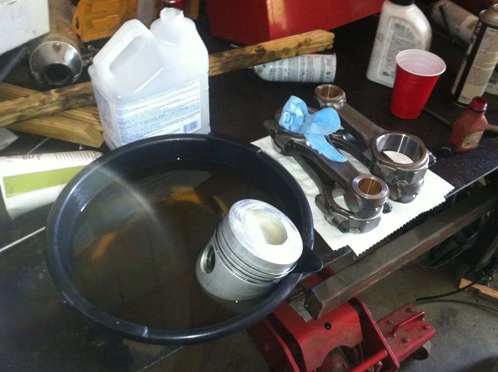
Time for the pistons to be installed along with the connecting rods first I cleaned the
With mineral spirits
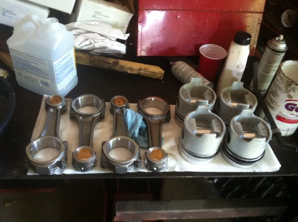
null-37.jpg

All nice and clean
null-38.jpg

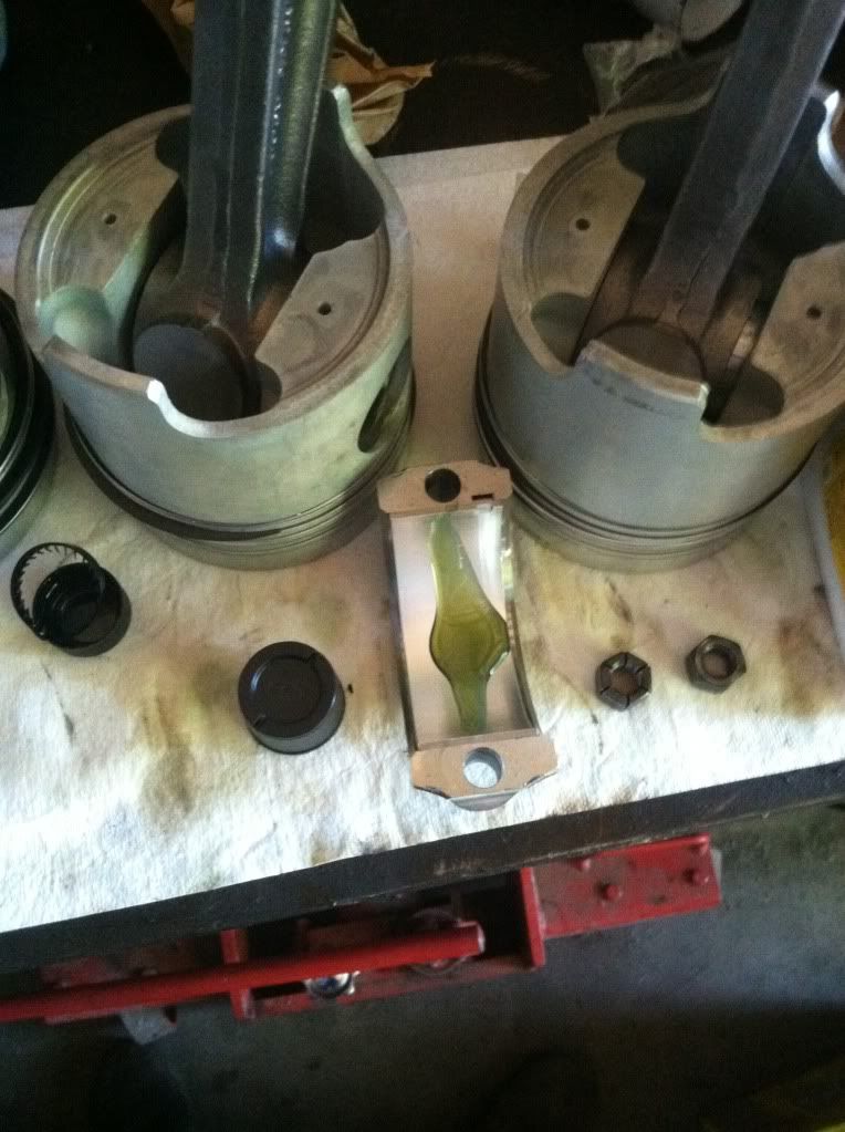
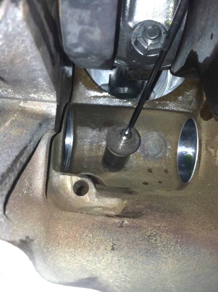
Some assembly lube lube every moving part you can these are where the wrist pin goes through in the piston and that's why holds the piston to the connecting rod
null-39.jpg

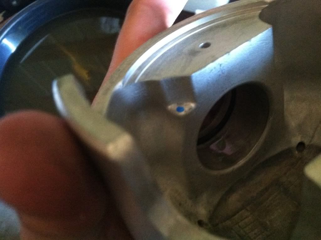
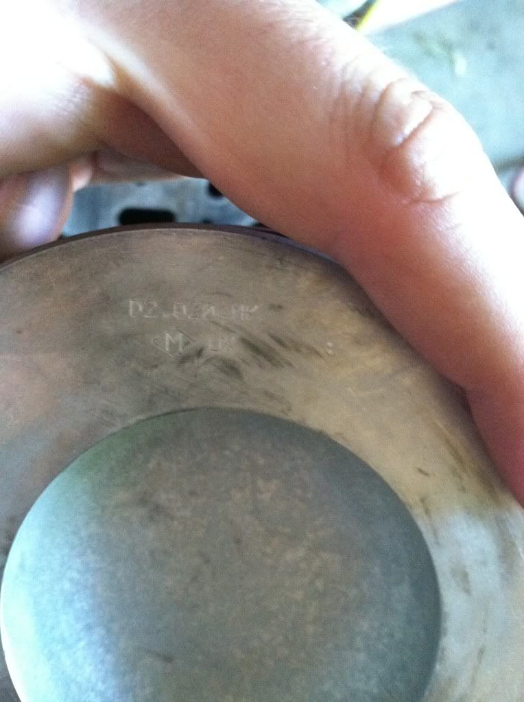
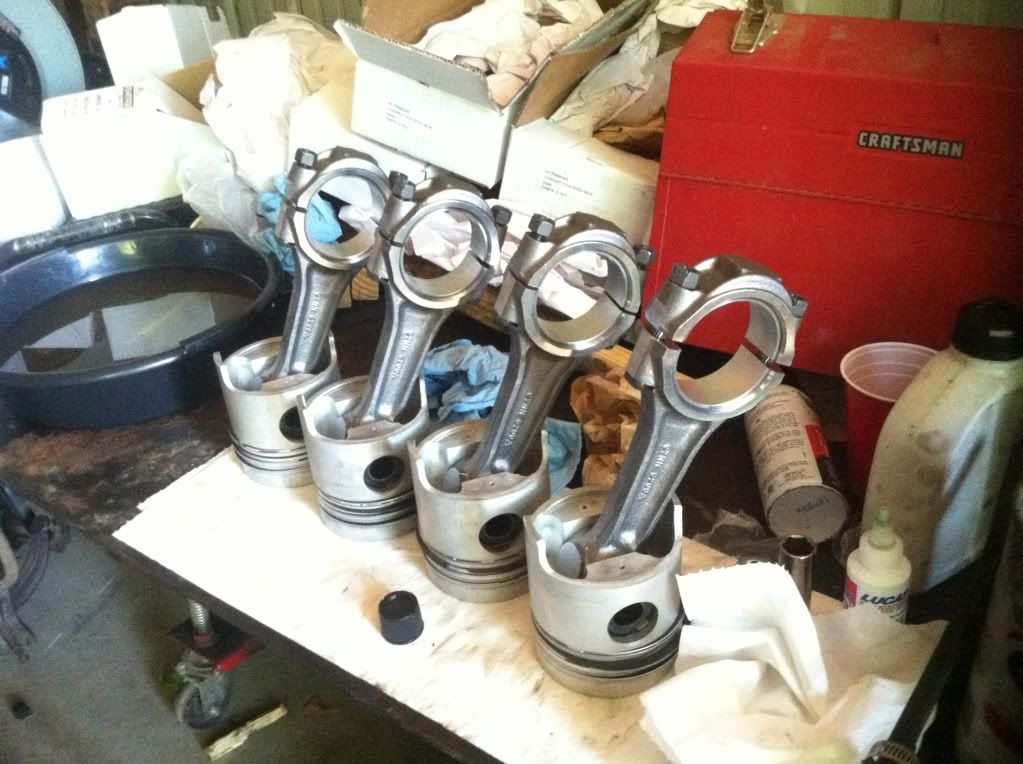
Not all pistons have this mark but these do th mark should point to the front of the motor factory pistons have a notch that point forward depends on who makes the pistons it does matter which way they go in
null-40.jpg

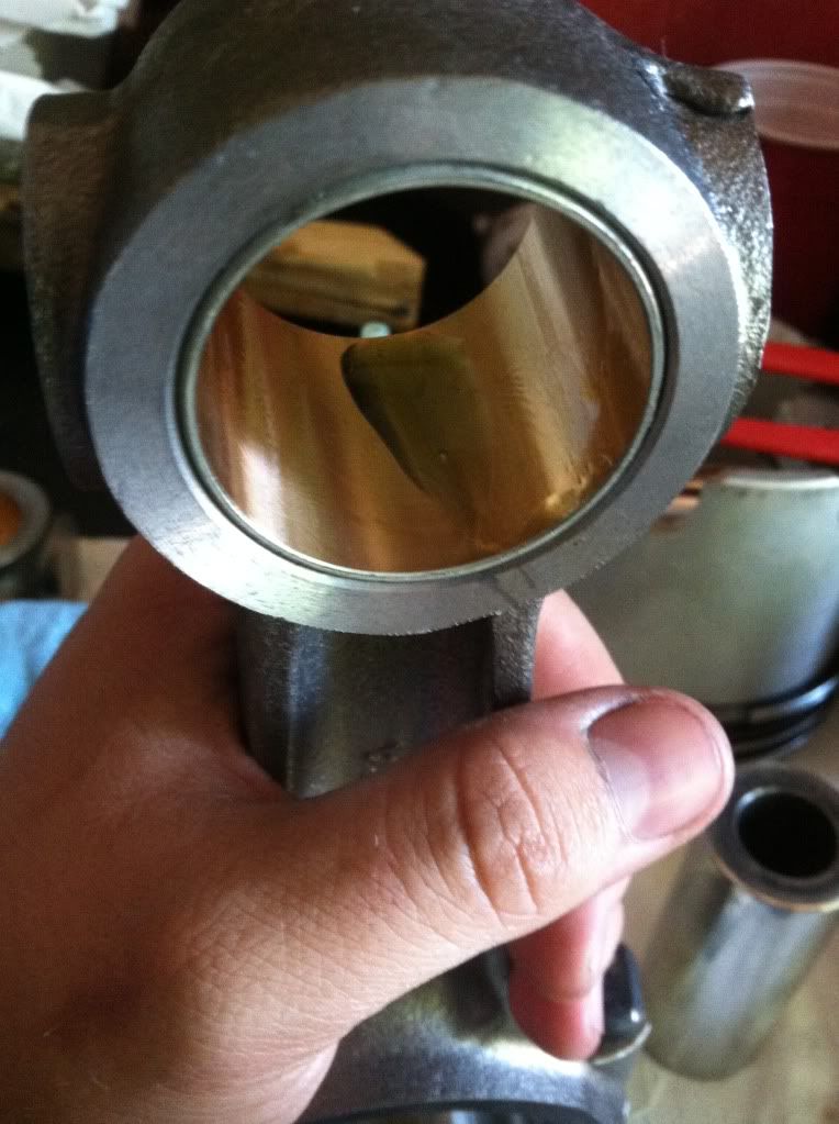
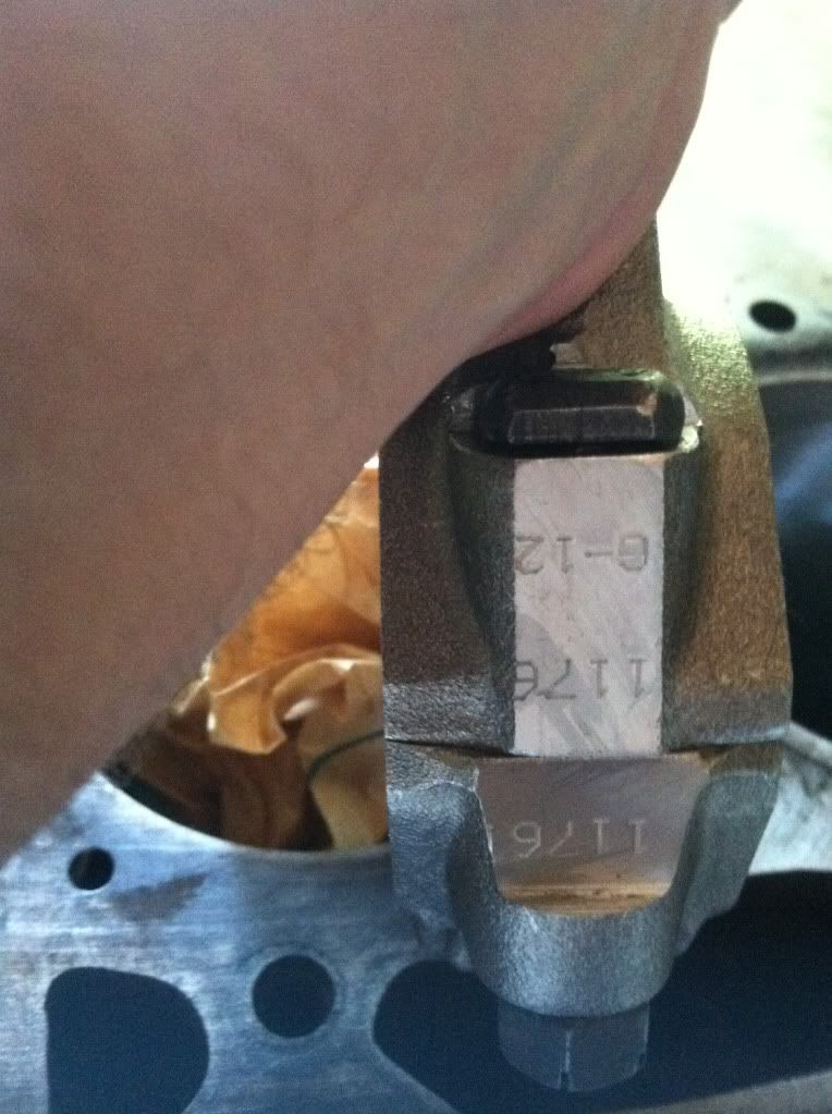
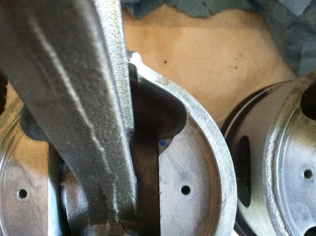
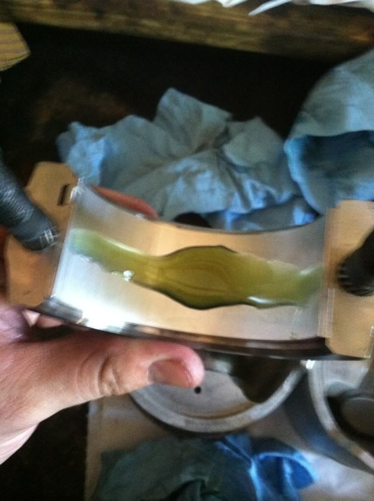
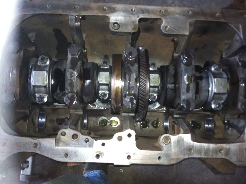
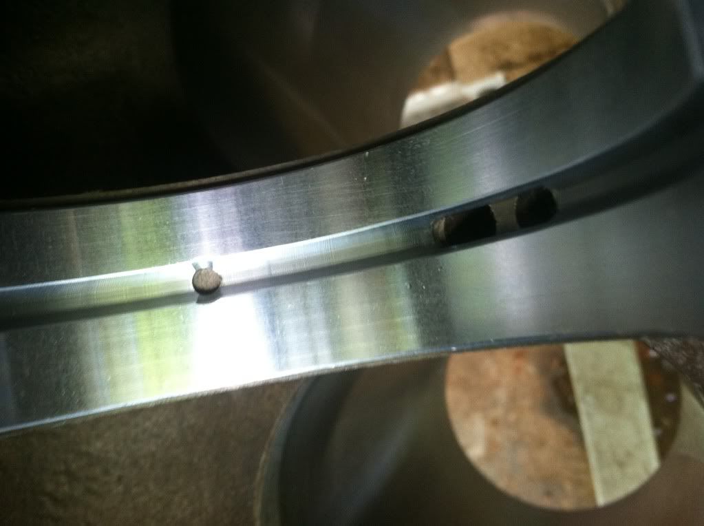
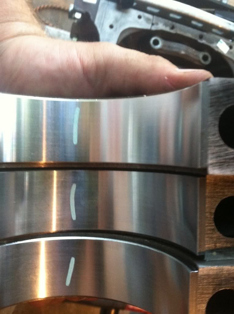
Also note the numbers on the connecting rods. when rods are taken apart numbers should be lined up same side like this picture. also when the rod is put on the crank shaft These numbers should point to the camshaft no clue why always have been taught that way. Must be because of the direction the bearings lock in.
null-41.jpg

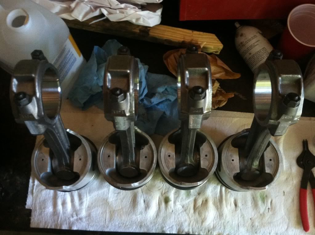
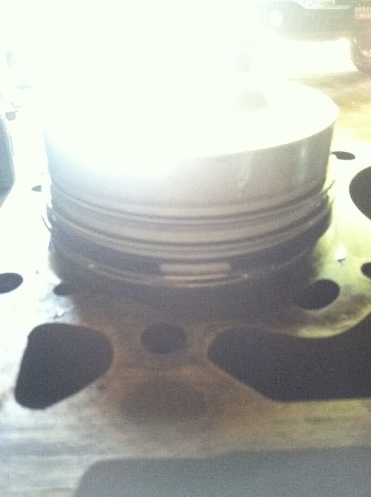
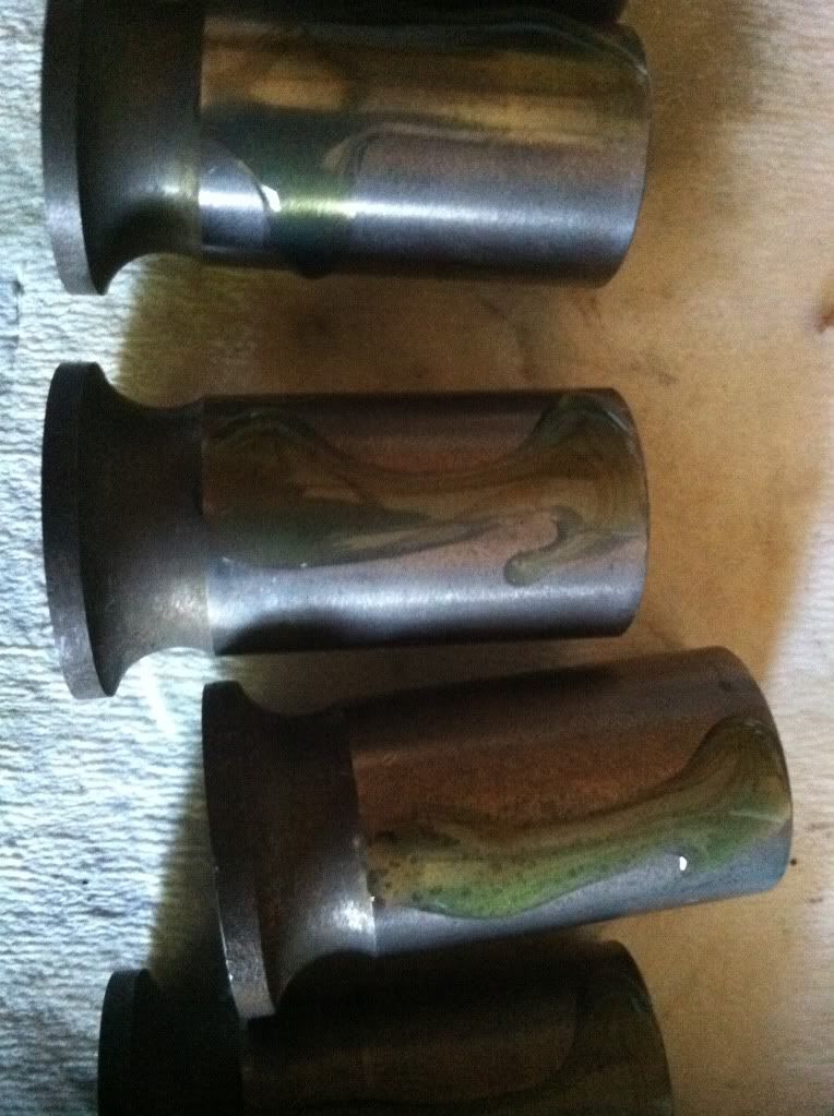
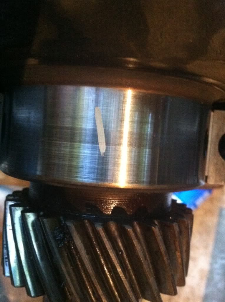
Piston size numbers my number pointe to the front of the block
null-42.jpg

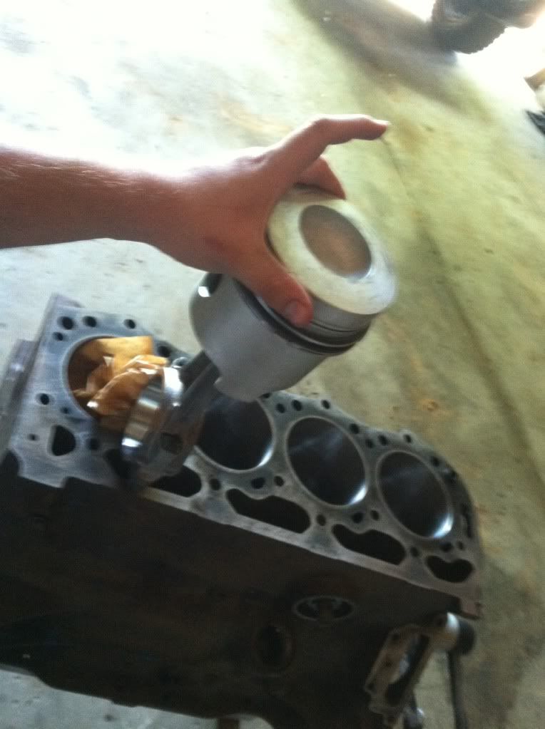
This is exactly how the piston will go in the rod numbers were pointing towards me the front of the motor is to the left in this picture
null-43.jpg

All assembled make sure you lube your wrist pins too
null-44.jpg

Notice the notch on mine they point to the front of the motor
null-45.jpg

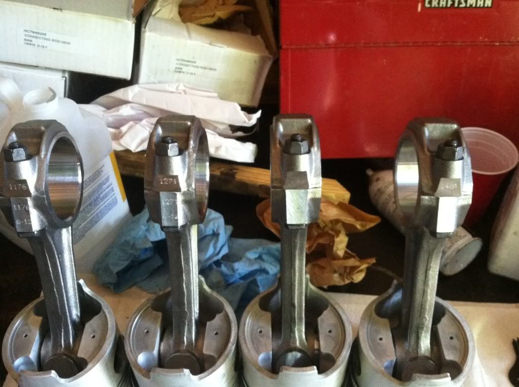
All connecting rods numbers are towards me the notch is opposite
null-46.jpg

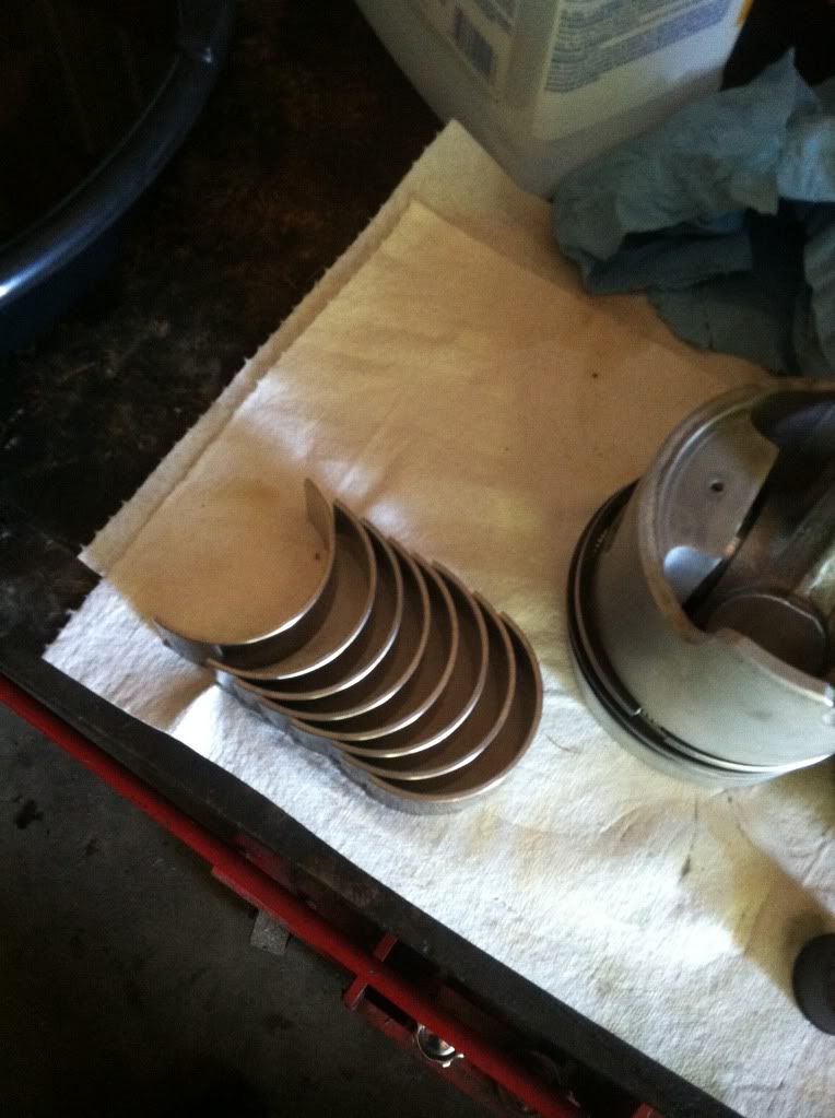
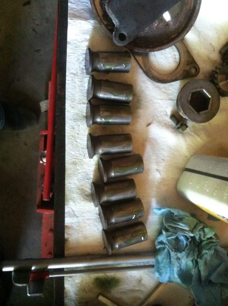
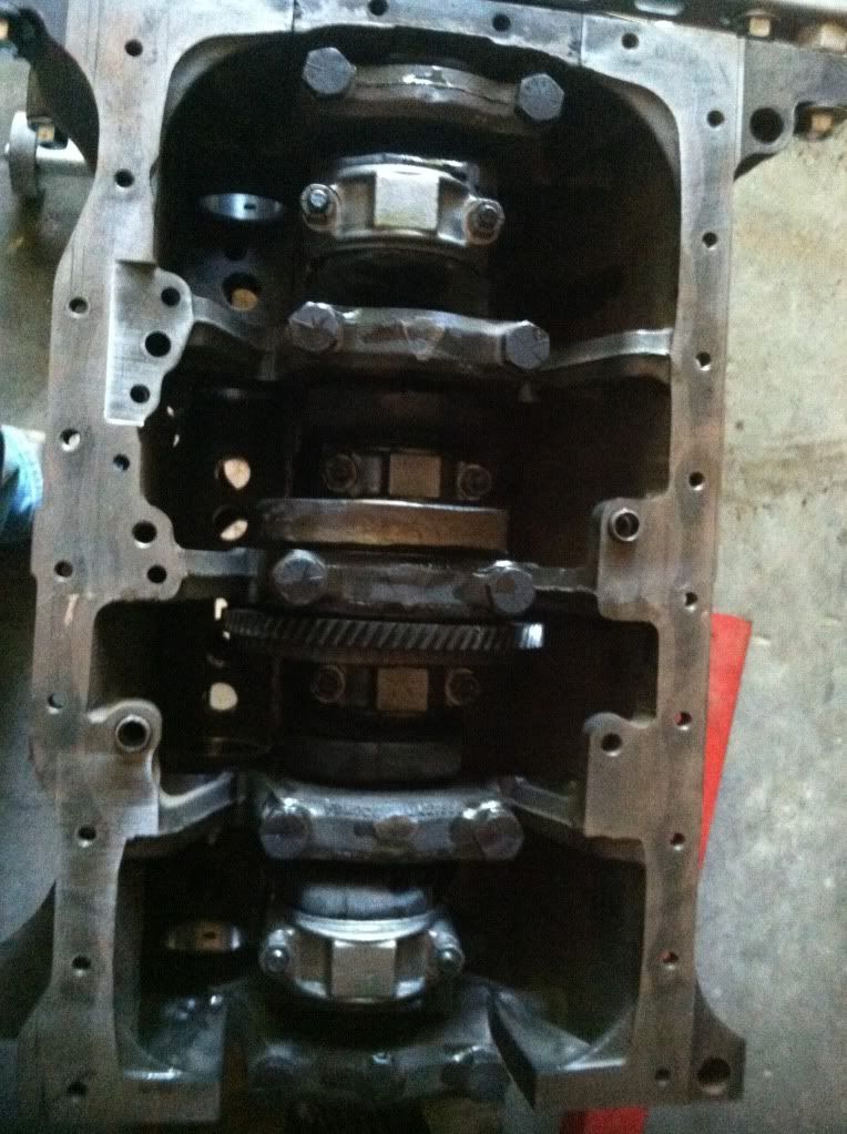
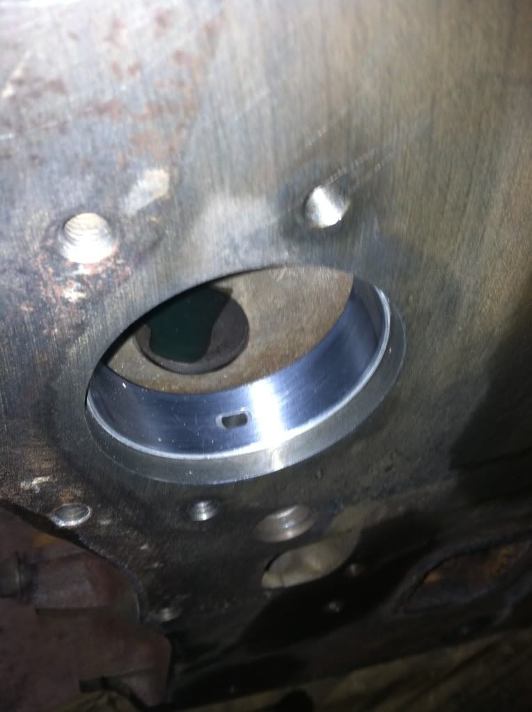
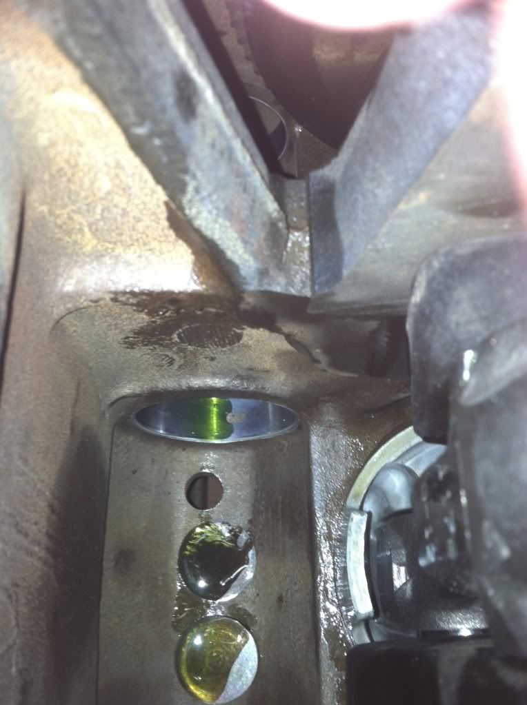
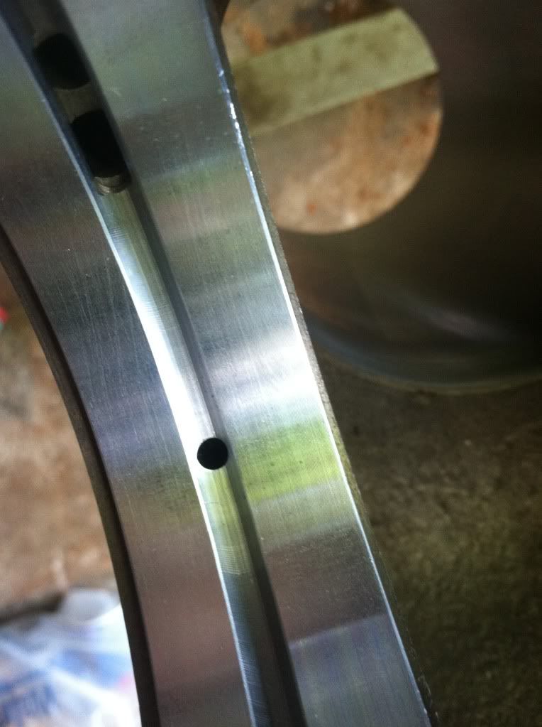
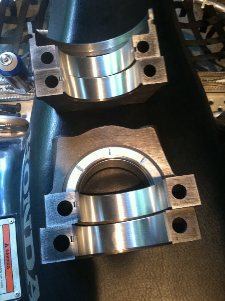
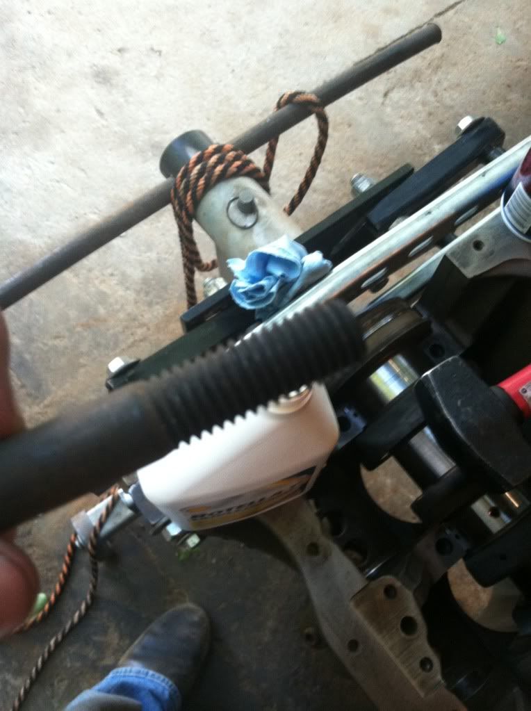
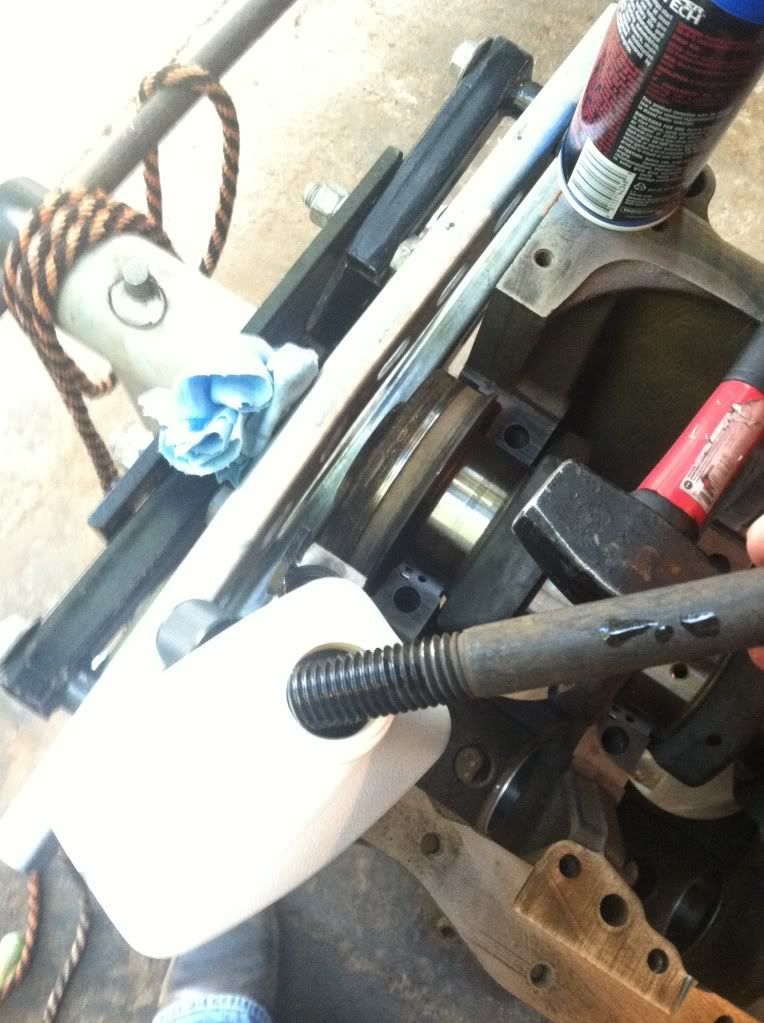
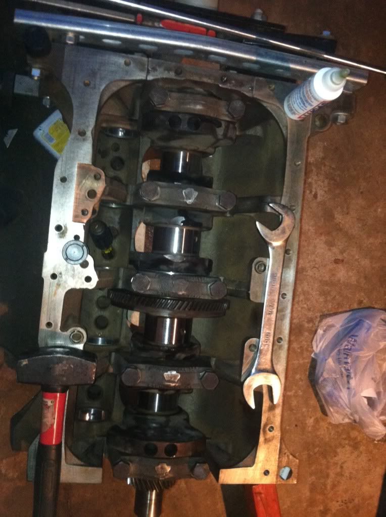
Installing all the bearings make sure they are nice and clean also be very careful not to knock them
null-47.jpg

null-48.jpg

null-49.jpg

null-50.jpg

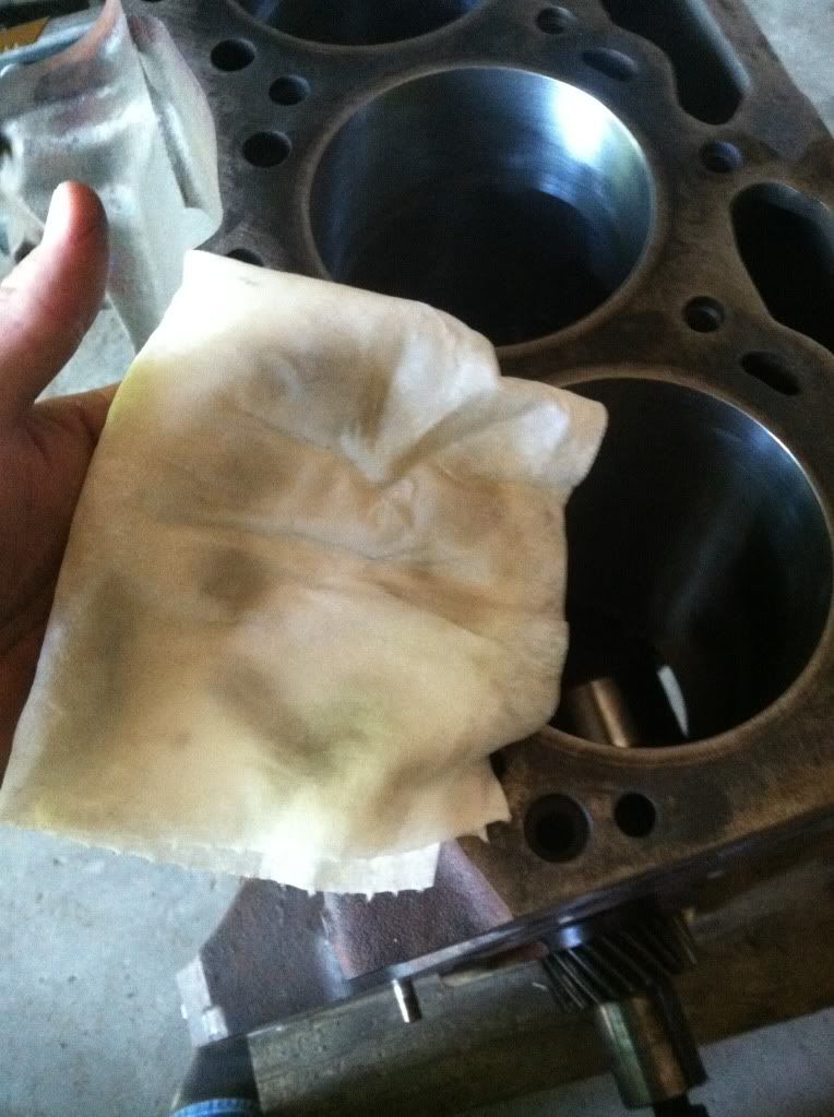
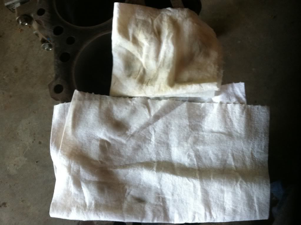
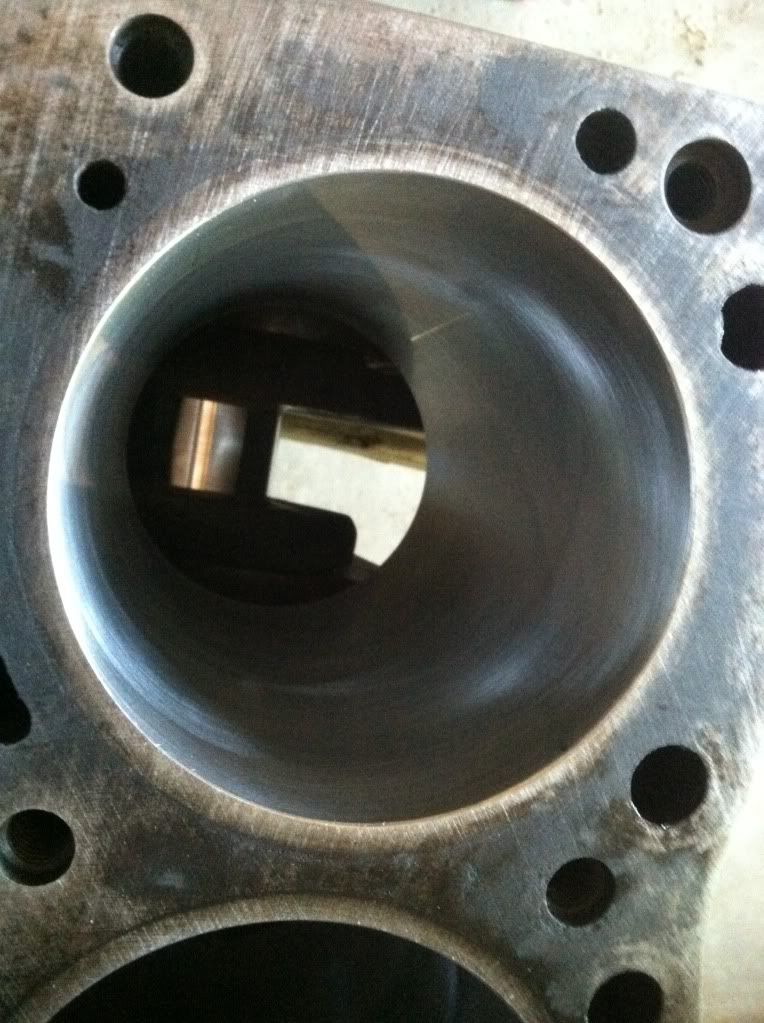
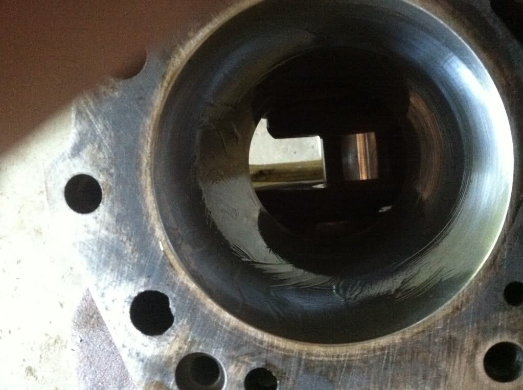
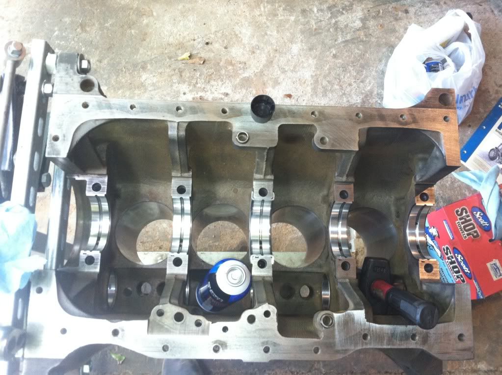
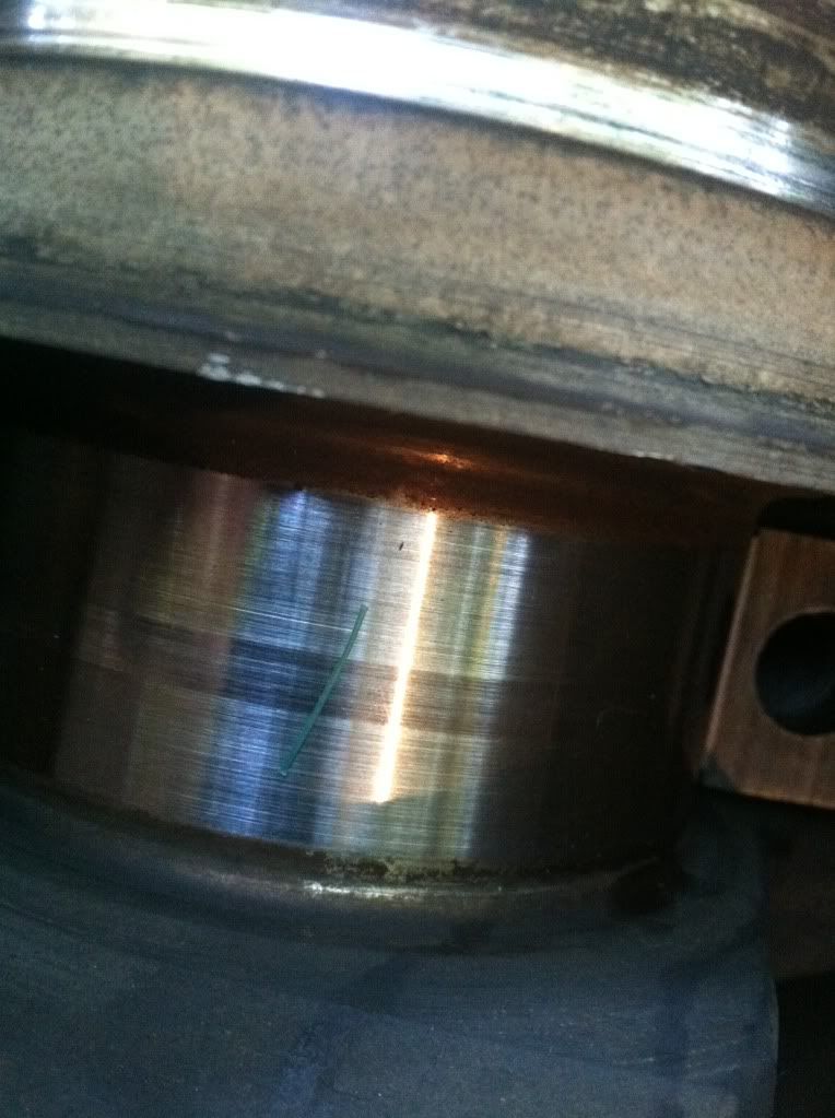
Next make sure cylinder walls are very clean no hoaning material should be left from the machine shop after its clean clean again with a white rag then oil down the cylinders walls and you'll be ready to Install your pistons
null-51.jpg

null-52.jpg

null-53.jpg

null-54.jpg

null-55.jpg

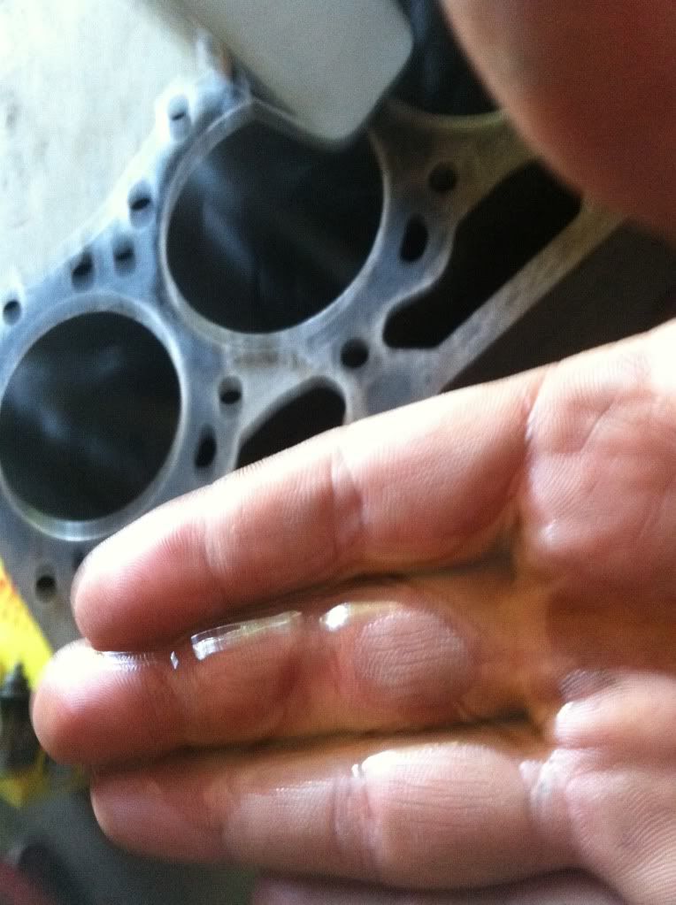
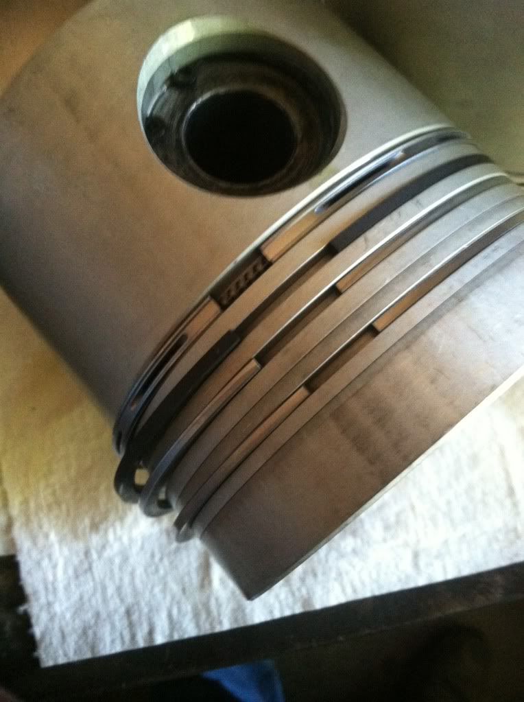
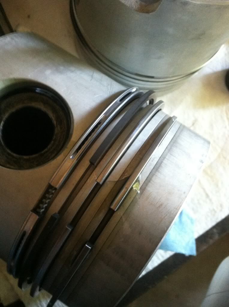
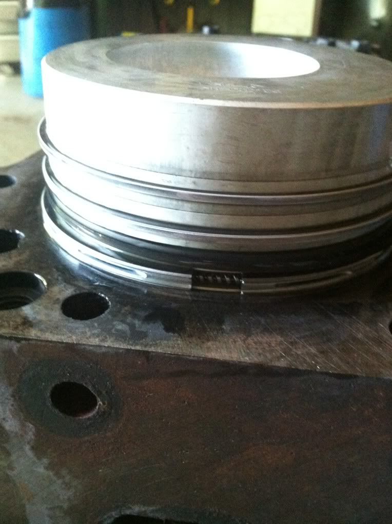
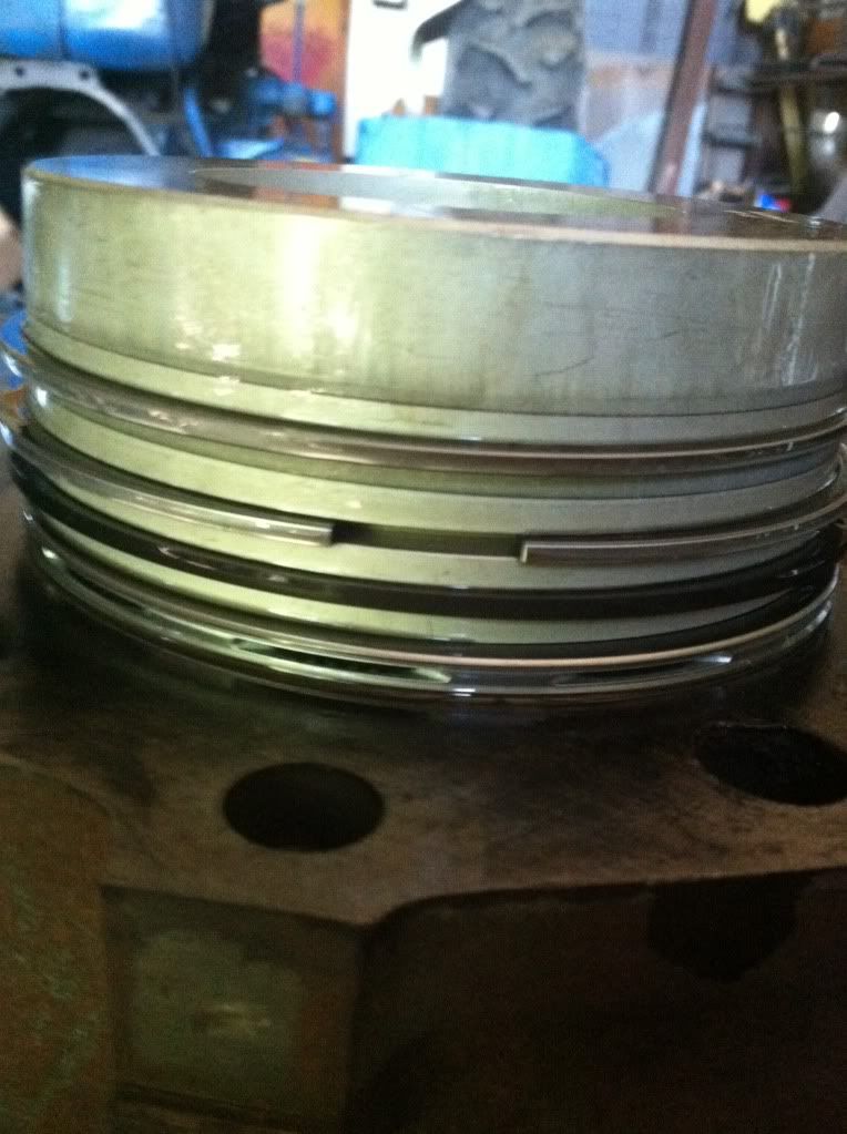
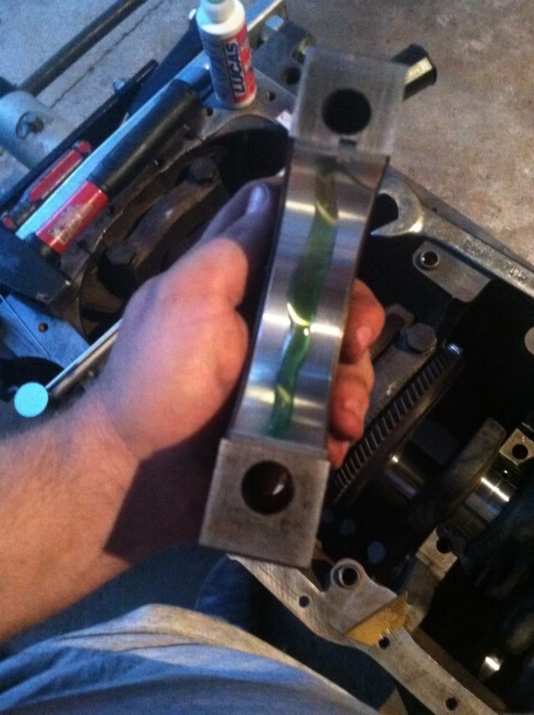
Next it's time to oil your piston rings for the initial start up line all end gaps and poor oil in the then walk the ring all around one by one till they all feel lubricated
null-56.jpg

null-57.jpg

Then it's time fore assembly lube on your bearing for your connecting rods because its almost time to install them after the tops and bottoms are lubed
null-58.jpg

null-67.jpg

Next slowly drop your pistone in and crank your crankshaft over so the journal is at top dead center or at its up most position. VERY IMORTANT line your rings up at opposite sides closest ring to your wrist pin which is your oil ring should be lined up to your wrist pin next ring up is a compression ring should line up to the skirt to the left or right then the third from bottom should be lined to the opposite skirt side the fourth should be lined up with the wrist pin on the opposite side of the first one.
null-59.jpg

null-60.jpg

null-61.jpg

null-62.jpg

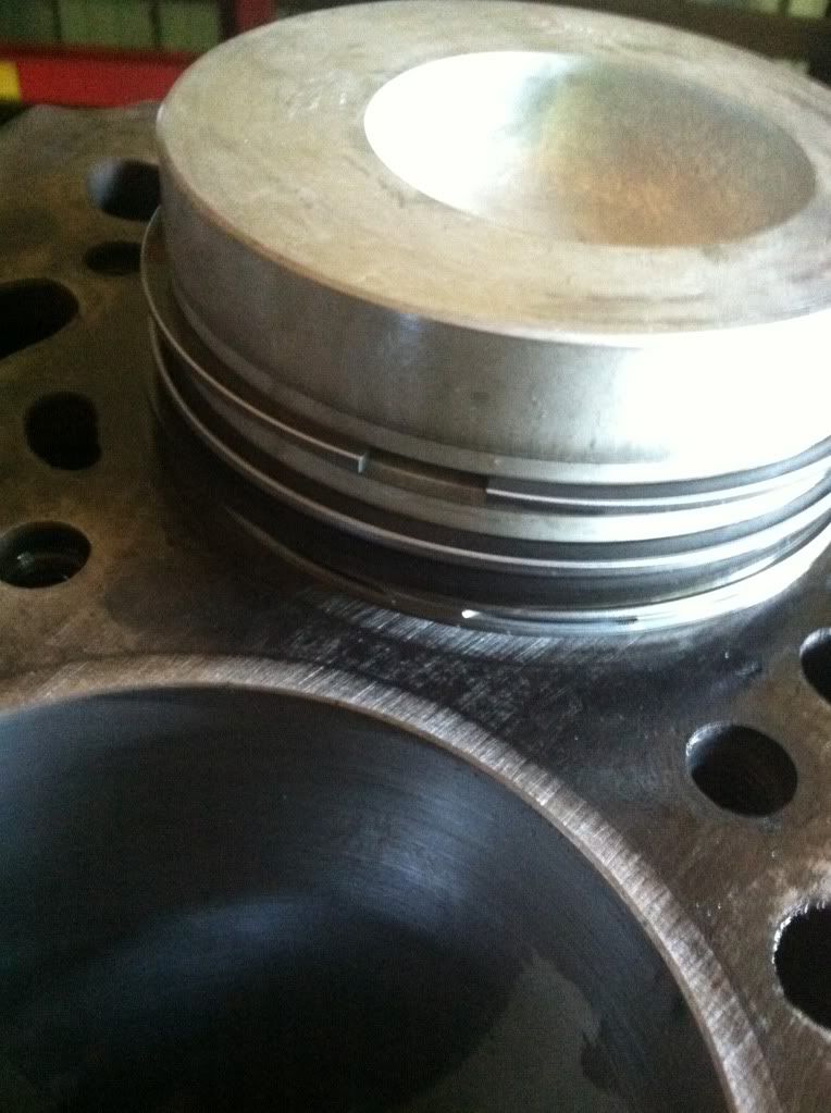
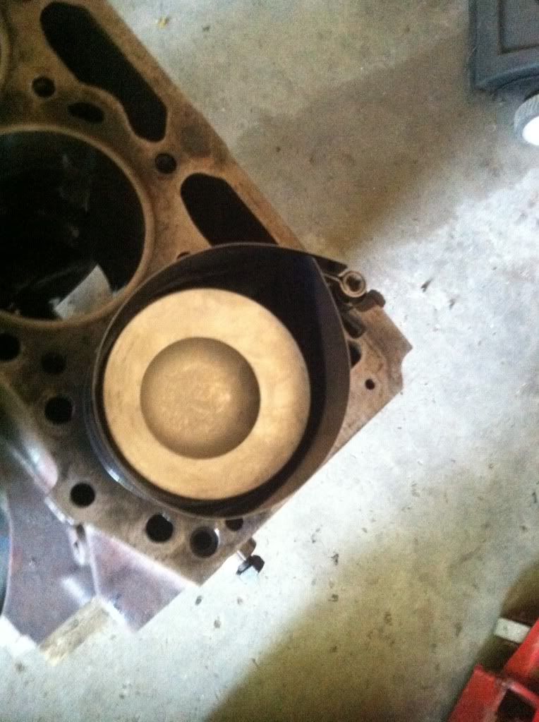
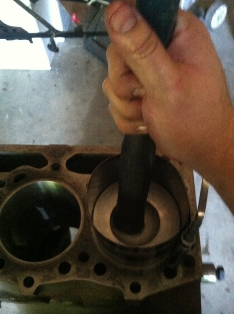
Now time for the ring compressor tighten it up and piston install time athen just simply bump it in with the handle of a hammer make positive cylinder walls are lubed good
null-63.jpg

null-64.jpg

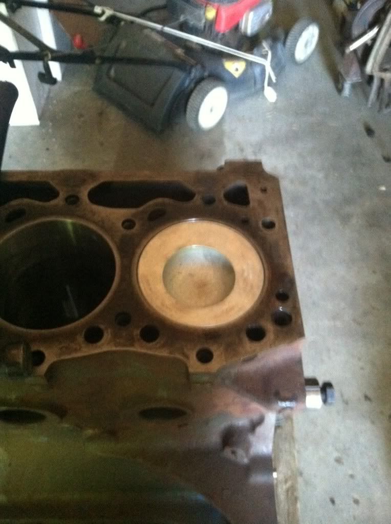
Nice and installed front of my motor is to my right now
null-65.jpg

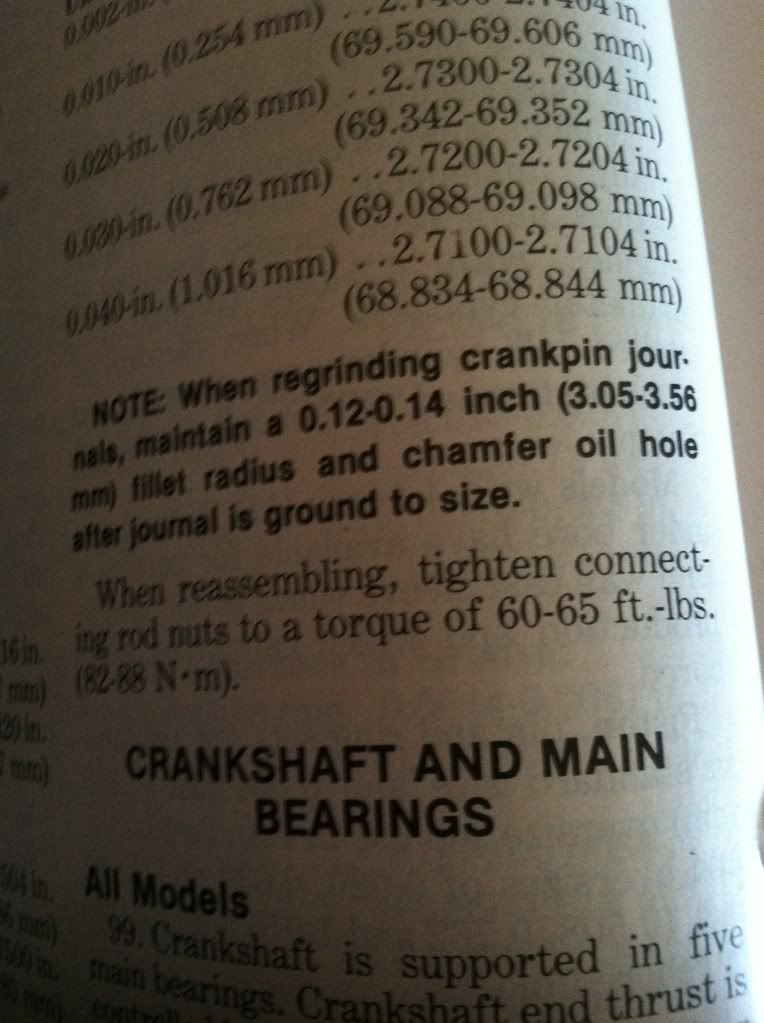
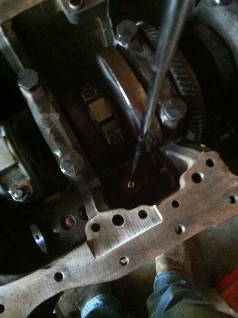
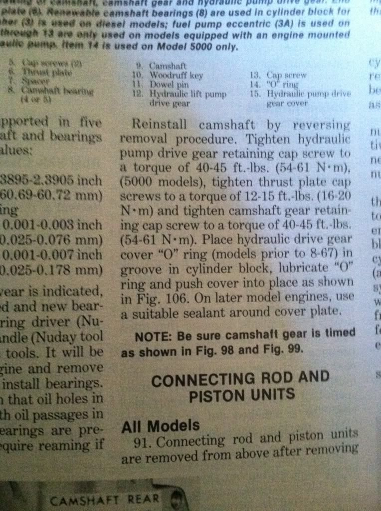
Connecting rods torque settings
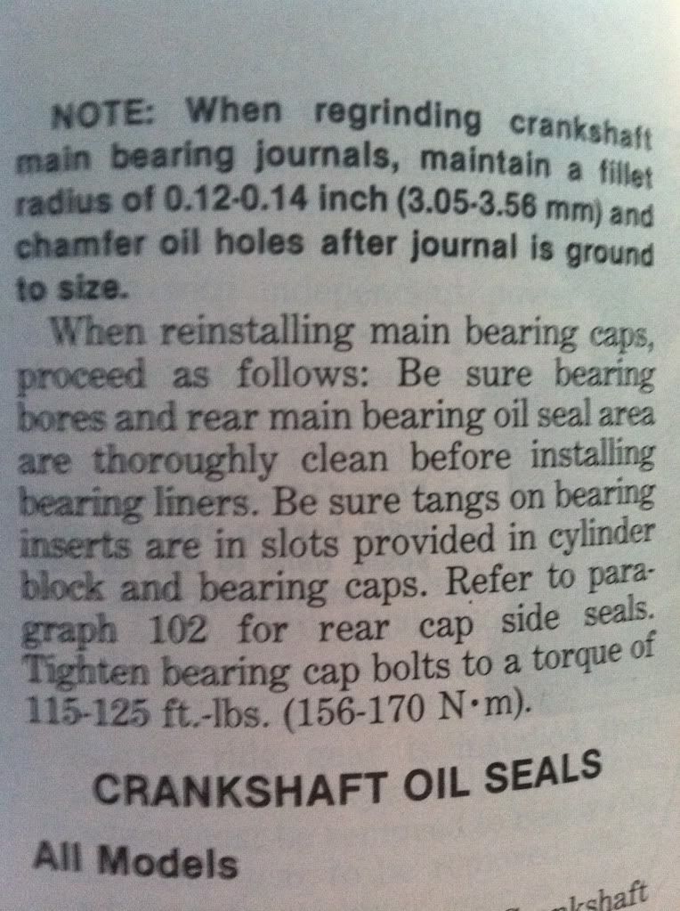
null-66.jpg
 
   / Ford 5000 restore
  • Thread Starter
#30  
Time to install the cam
First we start with the lifters I cleaned them then assembly lubed them when installing drop in with a magnet then spin them around a few time to work the lube in also put a dab on the bottoms where they will ride on the cam
null-68.jpg

null-70.jpg

null-71.jpg

null-72.jpg

null-73.jpg

null-74.jpg

null-75.jpg

Next time to install the cam. Clean bearings very good and coat with assembly lube slide cam in. Be VERY VERY CAREFUL when Installing the cam. Very easy to nick bearings with cam lobes.
null-76.jpg

null-77.jpg

null-78.jpg

null-81.jpg

Next time to install the cam holder this keeps it from running in or out there is a spacer and also a moon shaped key that goes on the cam to hold on the gear the torque specs are in the paragraph lube back side of gear as well
null-82.jpg

null-83.jpg

null-85.jpg

null-84.jpg
 
 
Top