Ford 1920 alternator output

   / Ford 1920 alternator output #11  
Jim, what's the old saying? "Be careful what you wish for...." My service manual covers the 1920 and 2120. The wiring diagram for the 2120 has the color code, so I've been trying to match colors to the 1920 diagram. I hope it helps.

Bob

Aargh! Now you did it! I have no excuses anymore.:D

Well, it turns out your glow plug operation is mechanized quite differently from my tractor. That should be no surprise really, but I am still surprised to see your circuit works as shown on your schematics. The most significant thing I can see about your circuit is that your Glow Plug Timer really doesn't time the glow plugs at all. All it does is time a warning light on the instrument panel. You have to observe the light going out and then move the ignition switch to Start. The timer just controls a visual indication for you. Also, when your ignition switch is moved to the Start position, the glow plugs are held energized while the engine is cranking. The glow plug timer gets that signal from the Neutral Start Relay and bypasses the timer to illuminate the glow plug light while the engine is cranking.

So, if you pull the glow plug timer relay, the only thing you are stopping is the instrument panel glow plug lamp. The glow plugs still operate with the timer removed.
 
   / Ford 1920 alternator output #12  
More research indicates you were on the right path with your alternator. Can you just pull the two conductor plug on the back of your alternator? If so, do that and see if you still have the fuse blowing problems. There's a good chance the test at Autozone may have missed an internal regulator partial short that is just enough to blow your fuse. If pulling the two-wire plug on the back of the alternator doesn't stop the fuse blowing, the next thing would be to disconnect the instrument panel.

Turning your ignition switch to Run or Preheat supplies current to the fuse. From the fuse, it splits and goes to the alternator's regulator and to the instrument panel. The schematic (1920 one) doesn't show it going anywhere else. The additional power routing is through the instrument panel's circuits. However, glow plug current comes directly from the ignition switch and is only protected by the main fusible link near the starter.
 
   / Ford 1920 alternator output #13  
If you are blowing the fuse on WL 0.5, you will need to isolate that circuit by removing the 3 conductor plug from the alternator and remove the bulb from the dash indicator. I would also remove the positive battery terminal.

After these components are removed from the circuit you will need to measure the resistance from WL 0.5 to ground with an ohms meter. With these components removed it should be an open circuit (M =Mega ohms scale).

If the circuit is open, plug the alternator back in and check the resistance and then the bulb.

If the bulb cannot be removed provide us with the ohms reading from WL 0.5 to ground (Volts / Ohms = Amps).

Mike
 
   / Ford 1920 alternator output
  • Thread Starter
#14  
Jim and Mike, thank you very much your assistance. I had to read your posts several times to make sure I understand what you're saying. The fuse only blows when the instrument panel is connected to the main wire harness. Does that eliminate the alternator? Thanks again.

Bob
 
   / Ford 1920 alternator output #15  
If the fuse blows when you connect your instrument panel, the problem lies with in your instrument panel.

I have had instances where the bulb it self will short internally.

Mike
 
   / Ford 1920 alternator output #16  
Bob, I agree with Mike about the instrument panel. In an earlier post you said that the fuse only blew when the panel was connected and I overlooked that. You also said that the instrument harness and circuit board were new. How much re-wiring did you have to do to the circuit board? Does the supplied harness have all the connectors pre-installed, or did you have to splice wires or do connector pin insertions? The problem with both the schematics you posted is that the wire colors are shown, but nothing is there for plug/socket pin number references. Also, I'm sure you know how nothing is there for showing the instrument panel's circuits. We are left to assume that the circuit board and wiring harness are identical to the original with no way to verify except using the 2120 wire colors. I think there's room for error there (stating the obvious. . . sorry).

I believe the way the circuit is wired is that the glow plug power goes to the instrument panel at the same time as it goes to the glow plugs. In the inst. pnl, the power goes to one side of the glow indicator lamp. The other side of the lamp goes to the glow plug timer. The timer makes contact to ground for the glow lamp to illuminate and holds that contact for several seconds until the timer runs down and opens the circuit so the lamp goes out. That's supposed to tell you that the preheat cycle is done and you can move the key to start. We never get to see if that circuit is working properly, because as soon as you apply power to the instrument panel with normal key to Run or Glow, the fuse blows. All this is intuition, but I think the problem is likely not with the glow plugs or that circuit at all. Something in your instrument panel is miswired and grounding your power from your battery and alternator. That's probably the reason the voltages never read correctly. I think the normal instrument panel power is shorted to ground. I just don't know what pin in the connector to say to check. However, if I can believe the 2120 diagram, it's a White/Blue (coded WL) wire going into the instrument panel connector. I'd bet that if you check that with the instrument panel connected, you'll find zero ohms to ground (shorted). You are on your own after that to check where the short might be in the instrument panel. If there is some way you can come up with an actual wiring color chart for the 1920, it could verify that all those colors are similar. What I'm seeing in the way the fuses seem to be wired makes me think that there could be a difference in the two models. For example, the 2120 shows power for one fuse coming directly from the hot battery bus while the 1920 shows all the fuses being supplied power from the key switch. That leads me to believe there are slight wiring differences.
 
   / Ford 1920 alternator output
  • Thread Starter
#17  
Jim, regarding the new parts (circuit board and harness) I didn't have to splice anything, they were complete. BUT they didn't match the original in that there are 2 or 3 fewer pins in the connector on the new instrument harness. The guy at the parts counter siad it was the only one available for my tractor.

The service manual states: "The key switch supplies electrical power to the glow plugs and to the indicator lamp and timer relay through two seperate circuits."

The only wire coming from the fuse that keeps blowing is white/blue. I'll keep reading your posts and studying the wiring diagrams. Due to work schedule I'll won't be able to look at the tractor until the weekend. I'll post what I find out. Your help is very much appreciated.

Bob
 
   / Ford 1920 alternator output #18  
Jim, regarding the new parts (circuit board and harness) I didn't have to splice anything, they were complete. BUT they didn't match the original in that there are 2 or 3 fewer pins in the connector on the new instrument harness. The guy at the parts counter siad it was the only one available for my tractor.

The service manual states: "The key switch supplies electrical power to the glow plugs and to the indicator lamp and timer relay through two seperate circuits."

The only wire coming from the fuse that keeps blowing is white/blue. I'll keep reading your posts and studying the wiring diagrams. Due to work schedule I'll won't be able to look at the tractor until the weekend. I'll post what I find out. Your help is very much appreciated.

Bob

Bob, finding out what is shorting that White Blue wire (coded WL) is the key to finding your problem. The pin on the end of the plug right next to the WL wire is Black (B). That's your ground wire as shown on the 2120 diagram. With the instrument panel removed, check continuity between the two pins in the connector. If you read zero ohms, your instrument panel is toast. If it reads open or a fairly high resistance, then your problem is probably external to the instrument panel and making contact through the plug only when connected. There's no real need to check continuity between those two pins in the connector that plugs into the inst pnl because when you disconnect, the fuse holds. Using the 2120 diagram as a go-by, you could check each pin's connections to individual components, but that is a VERY tedious process.

Did you ever mention what the value of the fuse is that you are blowing? I'm curious to know just how much current you are drawing. If it is a very low value fuse, I'd even be tempted to go up to a slightly larger value. Don't make any big steps in value. That's inviting smoke creation.

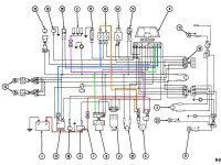
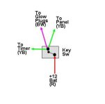
Yes, your svc man'l says there are separate circuits. Look at the diagram I've highlighted below. The red wire is the +12 vdc from the battery by way of the starter terminal. The power leaves the battery and goes up through the fusible link and over to the key switch. When you go to the preheat position, power leaves the switch on the pink line and goes up and over to the glow plugs (actually a black/white wire). Notice the green lines attached to the pink line on the diagram. I colored them green to make them stand out even though they are connected to the pink line. In the 2120 diagram, it says these wires are yellow/black. If you believe the schematic, somewhere between the key switch and glow plugs, there are two splices. In reality, the wiring is done like the small drawing after the schematic. On the back of the key switch, there are probably three separate wires. One to each component: 1) glow plugs, 2) timer, 3) inst pnl. I think that's what the service manual means by separate circuits.
1920ActualWiring-1.jpg
1920ActualWiring-2.jpg

Also, look at the color highlighted circuit for the fuse. Power comes up from the key switch on the amber highlighted wire. It leaves the fuse and goes to the alternator regulator and also over to the instrument panel. This is the circuit that is blowing the fuse and the source of your problems. It seems to have nothing to do with the glow plug circuit and is why I say the glow plug circuits are probably not the source of your problem.
 
   / Ford 1920 alternator output #19  
I am not convinced that autozone tested the alternator correctly. Did you verify it yourself that the alternator is putting out 14V or better into a battery?
 
   / Ford 1920 alternator output
  • Thread Starter
#20  
Jim, thank you for taking the time to highlight the schematic. It's a big help to me. The fuse that protects the circuit is 10-amps; if we went to 15-amps is there a great risk of a smoke show or other component damage?

DieselMonk, with the tractor running I was getting 12.2v at the battery and at the alternator. With all lights on it dropped to 11.95 at both. That's what made me think the alternator might be bad. If the alternator was bad, wouldn't that only be evident with the tractor running?

Bob
 
 
Top