Lucas CAV rotary injection pump math

   / Lucas CAV rotary injection pump math
  • Thread Starter
#21  
Today, I opened the pump for real

http://trixtar.org/3/tinkerings/12valve208hp/missing-weights.mp4
1 - 2 of 6 flyweights are missing (unless 4 in 6 slots is normal)

http://trixtar.org/3/tinkerings/12valve208hp/camring-race-worn.jpg
2 - Cam-ring race shows heavy signs of wear (1000 hours?)


http://trixtar.org/3/tinkerings/12valve208hp/camring-lever-tool.jpg
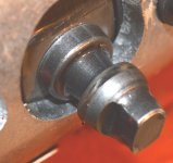
3- Cannot change it cause cannot remove this lever

http://trixtar.org/3/tinkerings/12valve208hp/worn-pump-drum.mp4
4 - Wear showing on pump drum:


All this in addition to the very large valve lash found earlier makes me think someone's been in there before
 
   / Lucas CAV rotary injection pump math #22  
Probably time for a new pump. What is the application for this thing, some kind of pump or gen set? I actually might question the hours on the thing also.
 
   / Lucas CAV rotary injection pump math
  • Thread Starter
#23  
Probably time for a new pump. What is the application for this thing, some kind of pump or gen set? I actually might question the hours on the thing also.

It comes from a fire-pump, it's going on a snow blower or...
 
   / Lucas CAV rotary injection pump math
  • Thread Starter
#25  
   / Lucas CAV rotary injection pump math #26  
1] 4 weights is normal..
2] Don't worry about THAT wear on the face of the cam ring.. its the lobes that are the wear portion..
3] That piece is called the cam ball.. it takes a special tool to remove it.. its made of soft metal & will round over if the tool is not used.. I've gotten them in rounded over & the trick is to clamp the "ball" in a vise & "smack/turn" THE PUMP..
4] Don't worry about the wear on the "drum".. THATS called the head & rotor assembly.. the part your showing w/ wear is the "rotor".. Absolutly no problem there..
 
   / Lucas CAV rotary injection pump math
  • Thread Starter
#27  
1] 4 weights is normal..
2] Don't worry about THAT wear on the face of the cam ring.. its the lobes that are the wear portion..
3] That piece is called the cam ball.. it takes a special tool to remove it.. its made of soft metal & will round over if the tool is not used.. I've gotten them in rounded over & the trick is to clamp the "ball" in a vise & "smack/turn" THE PUMP..
4] Don't worry about the wear on the "drum".. THATS called the head & rotor assembly.. the part your showing w/ wear is the "rotor".. Absolutly no problem there..

Obviously you've seen a few dandies :laughing: Mine might become one too, I can't even put it back together so if I ever send it to be rebuilt it's gonna be a box full of parts!

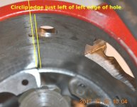
These are the only question-marks I found in the pump, I guess a pro would put it on the test-bench and find a dozen more on the gauges that I never could. The bad news is that if the pump is basically OK then I'm up the creek with very few other suspects, maybe the question of the circlip not being in the middle of the timing window under the 'cover-plate' where it's supposed to be, I still have to wrap myself around that one :mad:

According to one pro mechanic here "if the compression is 420-425 then there is NOTHING wrong with the engine itself". If I make a mistake I double my costs and that's no peanuts. When I first saw those marks I figured I might just replace the 'head-n-rotor' and the 'cam ring' on spec ...and see what happens (the transfer pump is already done). All the springs are like new, all in the correct holes, etc.

The one thing I find a little strange (mostly because this is the first pump I open up) is that everything that moves feels fragmented as opposed to other oil-bath mechanisms that just glide along, it might be a characteristic of diesel/heating-oil lubrication.


1
I wasn't sure because while a 4-cylinder Delphi C2126T manual shows 4, but the CAV manual shows a diagram with 3 adjacent ones.

3
It's the threaded part of that 'cam ball' that worries me, I've already put some big torque ft-lbs to it and any more will break the screw in the hole (I'm presuming it's turn-left to unscrew). I tried it in the wise but mine doesn't give the accessibility I need, I've already done some rounding. I'll figure out something. I find these manuals extremely flimsy and superficial

cam-ring-adv-screw.jpg
 
   / Lucas CAV rotary injection pump math
  • Thread Starter
#28  
..up the creek with very few other suspects, maybe the question of the circlip not being in the middle of the timing window under the 'cover-plate' where it's supposed to be, I still have to wrap myself around that one

ok, here's a nother one, THIS could be pay dirt:

http://www.trixtar.org/3/tinkerings/12valve208hp/half-pump.mp4

A pair of dead cam rollers would cut pump volume in half, I don't know what it would do to pressure though, and pressure being a dynamic auto-advance parameter.
 
   / Lucas CAV rotary injection pump math #29  
There are 2 pairs of plungers under/behind the shoes& rollers.. 1 long set & 1 short set.. the long set will move when you push the rollers, the short set wont..
IF you take them out for inspection, its important to get them back in the correct position.. not so much EACH plunger but in the correct holes in the head..
They are opposing plungers so long goes w/ long, short goes w/ short.. don't put a long w/ a short..
I noticed you took off the main fuel adjustment.. the gizmo that has the 2-12pt screws.. that sits on top of the shoes.. I sure hope you marked it..
The C clip in the housing wont ever be centered in the housing.. its moved for timing purposes..
 
   / Lucas CAV rotary injection pump math
  • Thread Starter
#30  
There are 2 pairs of plungers under/behind the shoes& rollers.. 1 long set & 1 short set.. the long set will move when you push the rollers, the short set wont..
IF you take them out for inspection, its important to get them back in the correct position.. not so much EACH plunger but in the correct holes in the head..
They are opposing plungers so long goes w/ long, short goes w/ short.. don't put a long w/ a short..
I noticed you took off the main fuel adjustment.. the gizmo that has the 2-12pt screws.. that sits on top of the shoes.. I sure hope you marked it..
The C clip in the housing wont ever be centered in the housing.. its moved for timing purposes..

And I thought I had found IT..

Unless I missed something, never more than 1 piston was out and then I put it back in the same place. But on their way to the glass full of lamp-oil two of he rollers fell on the shop floor, I found one in minutes but the other one only after an hour of vacuum-cleaning the floor because it had never fallen off the bench. That adjustment-plate has notches in the edge identical to the plate underneath the pump core, I was relying on those for re-alignment, didn't mark it otherwise. As for the circlip the manual says to place the marker edge near the window center, I wasn't sure where that road would lead so I took a snapshot

circlip-edge-position-1000.jpg


At the moment of the false flash-in-pan my idea was that IF something was amiss in that assembly then I would get a new one; the whole rotor/head goes for around $150.

The biggest problem is that now I'm back to square one, as far as the TS goes.

Have a nice weekend, I think I'm gonna do something else for two days and then come back with a fresh and positive attitude ...and my 10 pound sledgehammer :laughing:
 
 
Top