new tractor idea possibly....

   / new tractor idea possibly....
  • Thread Starter
#121  
100th diagram...

boggen new tractor idea100.png

ouchers... i am completely out of ideas... of how to deal with the implements... on this new setup.

is there 2 hyd cylinders on each side. and they play hot potatoes. and pass implement back and forth between them when implement is up above the STB, to move implement from one side to other side...

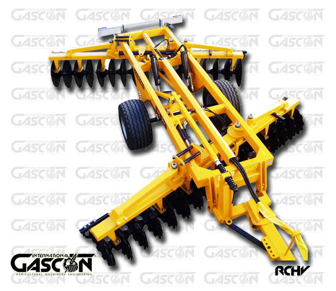
discs would be fairly easy, just a hyd cylinder or 2, and you can quickly adjust angles of all the gangs of discs.

but for chisel plows, rippers... were they are J shape. planters that have boxes... and some sort of spring that pushes down into the ground... reset springs for plows / rippers...

there is normally a single pipe that goes entire width of the implement. and chisles / rippers / discs get hung off of. perhaps instead of using box shape pipe. going with pipe O in shape. so these rows can be rolled over per row 180 degrees.

to state it, some sort of "crane" that does the moving of each implement from side to side and also turns implement 180 degrees...

does the STB act like a earth worm. getting shorter in length in field mode. and then longer in transport mode. and this switch from short to long. involves implements rotating from side to side...

is there 3 sets of hyd cylinders. 1 set on each side, to raise / lower, and adjust implement when it is down in the soil and then the 3rd set to flip the implement over to the other side...

i guess i am off to google regular old trains. and see if some pictures / video's give me some ideas... due to at this moment completely stuck in my tracks :/
 
   / new tractor idea possibly....
  • Thread Starter
#122  
*rubs chin* thinking about it.... perhaps a different setup needs to be considered... for the wheels. to keep the "height" of the wheel modules. from not being as high. so more of a "over the wheels" flat bed trailer type of setup could be done. but without the sheet metal / lumber for actual floor of the trailer. just the frame work... and supports for holding implements.

i realize large AG type tires always looks COOL! but really... can you get away with say 2 feet in diameter tires. (2 feet high tires)

ya agriculture / field tractors will see mud. but if a field is that wet... are you really going to be out there in the field making ruts?

about only thing that would come close would be furrows when using a bottom plow. but even then. you should be sinking tires to the axle that goes into a wheel.

i guess other thing would be "ground clearance" when units go up and down steep hills... were the distance between each wheel module would have to be considered.

===============
trying to justify things....

if i go with a train flat bed like trailer unit. and keep ground clearance say 12 inches. and wheels are 24" in diameter plus another say 6" above wheels to keep mud from clogging up on things. 24 + 6 - 12 = 18 inches.

i would most likely need to go up few inches above each wheel, to deal with 360 joint. lets say 6" inches and then a few more inches to deal with a drive shaft or hydrostatic transmission or electrical motor. lets say another 6 inches.

24 + 6 + 6 + 6 - 12 = 30 inches between top of the flat bed, and ground clearance. i could fit hyd cylinders that move wheels in and out for weight adjustment, engines, fuel tanks, radiators, hyd oil coolers. in that 30 inches... this would really lower COG (center of gravity) from being high up. to really low to the ground. and reduce tipping.

=================
i would imagine the frame work between each wheel module. could some how be done to extend or contract the frame. so different width implements. could be done up. some implements require more HP, traction, weight, while others do not.

it is not like farmers have not seen wagons and some implements that you can adjust length wise in the frame work. and it is left to the farmers to adjust distance between axles on a wagon, to put a flat top wood or metal deck on them...

but for STB tractor. this length adjustment may only happen between switching implement types...

==================
some pictures from a quick googling for "train equipment" and then clicking over to images....

got a kicker in thinking about this huge long crane (what ever special name it has) swings multi implements from side to side. then i thought about the weight placed in that single spot... *waves by by to the crane base as it sinks to center of the earth*

below image is from Assorted Brass Work Train Equipment and Specialty Cars | OVERLAND MODELS/ORIENTAL LTD., CA. 1980'S AND 1990'S | Maritime Pictures Auction</li>

d4846367r.jpg

===============================

gave thought to implements folded up on the STB during transport mode.

Old Train Equipment Of The Pichi Richi Railway Stock Photo 56817349 : Shutterstock

===============================

not really sure about. looks to be some sort of "man lift" to work on over head signs and signals that may go over a railways... thought maybe some sort of 360 spin to spin implements from side to side..*shrugs*

below image is from Railroad repair equipment. South of Rome, Italy - sprockit's Photos

144767599_WDTEY-M.jpg


===============================

maybe some sort of crane is used to move implements form side to side and into transport mode. and thinking maybe some sort of quick attach thing instead of a generic chain hook...

below image is from Lifting and rigging Australia. Allways Rigging. Rail lifting equipment

Franck-Marczan-Managing-Director-Allways-Rigging.-Lifting-and-rigging-Australia.-Rail-lifting-eq.jpg

===============================

MULTIPULE images from same webpage....

below 3 images are from http://www.raillynews.com/2012/07/10/

gave thought to going with "flat bed" trailers and shrinking overall height at the wheel modules.
ultrasonic-test-train.jpg


gave thought to a mount crane on the STB... don't know about this...
Brado.jpg


had to post it, grain wagon on train tracks.... if you could only remove the tracks...
Globaltrans.jpg


=====================
i have seen it done a lot of times more so on youtube and google images. and that is some sort of excvator or skid steer loading itself onto back of a trailer. without ever putting ramps down.

the below picture gave me thought, if cranes are used to move implements from side to side and place into transport mode. why not use the crane to act like the "links" between each section.

other words, if ya using a crane to move implements back and forth they will most likely have some sort of quick hitch / connector on them for implements. why not take things one step further, and put quick hitch on ends of each section for crane to attach to...

below picture is from Triad Online Training 08-10-07

479th_ARTEP_Training_300x.JPG

=====================
when i saw this, it just gave thought to all the actual physical training equipment out there. and the ways the use weights, bands, cables, wheels. to transfer things around... perhaps a odd ball crane something like below image ?!?

below image is from FreeMotion Equipment|Body Tech Dallas, TX
freemotion.jpg

=====================
this website gives a bunch of scaled models of train equipment. and just easier to give link to pages. vs trying to link to individual images...

Model Train Maintenance-of-Way Vehicles Page 3

Track Equipment Set - Kit - HO-Scale (dng100) Durango Model Train Maintenance-of-Way Vehicles

National Telescoping Boom Truck Body - Kit (unpainted metal) -- Fits Atlas Ford Truck, sold separately - HO-Scale (cfn7060) Custom-Finish Model Train Maintenance-of-Way Vehicles

Maintenance-of-Way (MOW) / Work Train Equipment (Unpainted Metal Kit) -- Kershaw RCH 100 Mobile Wrecking Crane w/Decals - HO-Scale (cfn7030) Custom-Finish Model Train Maintenance-of-Way Vehicles

had to special this crane out. due to to keeping the boom, dipper, and (bucket i guess) all extremely low to the ground and a long reach...

below image is from Maintenance-of-Way (MOW) / Work Train Equipment (Unpainted Metal Kit) -- Swingmaster Speed Swing Model 181 - HO-Scale (cfn7007) Custom-Finish Model Train Maintenance-of-Way Vehicles

cfn7007.jpg

=========================
one last thought is the mini excavators. the backhoe on them, could be considered a crane i suppose.

all i have for now... posting before i loose entire post....
 
   / new tractor idea possibly....
  • Thread Starter
#123  
*rubs chin* it needs to be stated one more time, to get it stuck into my head. unlike typical trains on tracks were there is massive engines pulling everything behind them. for the STB (side train box) tractor, the engines need to be split up across the entire length of the STB. main purpose is to spread out weight across all tires. provide backup with multi engines. reduce require massive size electrical wires and hyd hoses/pipes over entire length by supplying what is needed electrical and hyd power by a near by power source...

hhmmss...
the "engine section" shown in previous posts. really is not setting well with me.

current implements that fold out to 20 to 60 feet width normally have a massive structural support to support weight in transport weight, and then able to handle forces when implement is folded out...

the STB. would be just using the same extra massive structural support and re-designing it. to work with the STB. hhmmmsss....

=================
how deep would someone want to till the old stalks and stems from last crop into the ground. so next crop could be planted? thinking of out of box, of completely different way to till / plant field crops....

if STB could pull a roll over scrapper. or box blade, or 3pt hitch dirt scoop... could you move the dirt onto the STB. do what ever with it. and then drop it back down...

=================
quick note: when ya google images, and one of your own diagrams show up, you just gotta wonder...

=================

before i posting more pictures found from google...

why not make a circus act out of each section... not a laughing matter either...

with the wheels being able to do 360 spins. and all the latest techno out there... have each section have a wheel module on each end. and have the links between each section disconnect, and have each section do a 180 degree spin. and then each section reconnects. *calls up government* for military laser guided missiles, and gets a discount for the laser guidance system. to place on each end of a section... to make things easy to align up and all computer...

barrow stuff from the mail sorting industry, paint a special markings on each end of implement, let camera pickup up on it. and guide the links between each section as computer turns and moves the wheels per section.

not really liking this idea, way to many things could go wrong more so on uneven ground, and more to the point ground that could be wet, rutted, while other sections hard as a rock. farmer would be having a tow truck on side of field paying by the hour.....

================

folding 3pt hitch cat 1 / cat 2 / cat 3ish setups... shows more of the bare bones of folding...
= ORTHMAN MFG. - FENTON REPAIR

=================
think perhaps 2 rows of discs, some chisles, all in a narrow width setup. and then attached to a backhoe/crane. and instead of bucket = implement, and there just multi of these going down entire length of STB.

below picture is from V-shape hydraulic folding disc harrows RCHV

hydraulic_v_shape_carried_disc_harrows_1.jpg


=================
good amount of other pictures. the kinda double train caught my eye. and overlap of wheels in the center.

below image is from Valtra Ants Tractor by Lighthaus | Tuvie

valtra-ants-tractor-by-lighthaus2.jpg


=================
the cab really caught me off guard. reminds me of a carnival ride. how it rotates around and up... hhmmss... and then entire machine can lift up higher giving more ground clearance. different..

below image is from Marauder Dozer by Jon Pope | Tuvie

marauder-dozer-by-jon-pope1.jpg


=================
just closed the page, and caught picture at the very last moment. never really thought about "angling" the wheels and tread on them. hhmmsss.... conveyer belt as tracks... na.... angle wheels ya... wider diameter but less physical height... ok maybe just a quick impulse thought...

below image is from UVO : Urban Vehicular Ovalon by Alexei Mikhailov for 2021 | Tuvie

uvo-inner-city-megapolis-2021-vehicle2.jpg


====================
instead of some future vehicle. turn the passenger area into a hydrostatic pump or electrical wheel motors?

below image from 40 Years From Now, We Might Drive 2F2 Electric Vehicle | Tuvie

2f2-vehicle2.jpg


======================
ok i had to look just looked odd ball in thumb nail. something different that hyd cylinders... *shrugs*

below image is from Redesign Forklift Truck For Better Lifting and Maneuverability | Tuvie

forklift-truck-concept2.jpg


======================
looking at different crane possibilities, and saw this boom pole thumb and that HA!

below image is from Tractors and Farm Equipment

050.JPG


=======================

been thinking about folding up.. but this takes things i a new level!

but what about "roll over implements" you have ramps that let ya drive front or rear wheels right over a "finishing mower" on a lawn mower. to attach / unattach mower. why not let STB drive right over implements and then attach up to them... ok maybe not but *shrugs*


Uploaded with ImageShack.us


Uploaded with ImageShack.us

===================
do chisels, bottom plows, discs, and like really need to be on rear side of vehicle and be pulled? or can they be pushed? push stuff on one side, and pull stuff on the other side.... for single pass doings?!?

below image is from Road Drag can be pushed or pulled by truck or tractor., Paul Wever Construction Equ

452989.jpg


=================

not able to get picture directly. different way perhaps to move implements side to side?!?

Strange dual boom drill
 
   / new tractor idea possibly....
  • Thread Starter
#124  
boggen new tractor idea101.png

seems like a lot of motion and time to get implements swapped from one side to the other side.... as in minutes...

i am not sure what would be best for any given farmer. there are so many "shapes" and dimensions of fields. and what to do to make best use of the STB.... as in were to turn and were when to rotate implements to other side and scoot down the field how ever long the STB is and start going back down the field vs doing a long 180 degree turn....

when to split STB up into 2 or more sections. to do ends of fields and like.

i would imagine.... if 2 cabs (one on each end) a farmer in each one... on them much longer setups. one person keeping eye on direction, while another keeping on eye implements and gauges / cameras... *shrugs*... just do not know...and would down to individual field / farmer / and what would make the most use of it all...

================
perhaps main implement is on one side. and just a counter weight implement is on the other side... if needed...

then again if just going with implement on one side and not wanting to due 180 turns to get implement on other side. it would most likely make the entire frame work weight much, much less... that alone may be something...

back to drawing board to see what else comes up...
 
   / new tractor idea possibly....
  • Thread Starter
#125  
i am use to soy beans, corn, hay.... figure i better get into other things to see what the required....

came across a video. that does exactly what i am thinking about...

approx 3:00 or coupe seconds afterwards. it shows a wheel spining 180 degrees. though for STB tractor i would want it to do 360.

video from... T3


========
i never really thought about it... and that is wheel spacing... or rather "how wide" the wheels are compared to the crop rows.... in previous diagrams for wheel modules. i had 1.5 feet width wheel, and 2 of them side by side for of total of 3 feet plus the shaft coming down..... but... that might be a tad extreme for row widths... so.... needing to come up with a way... to make the 360 joint down to the wheel kinda of a universal swap out... form dual wheels. to single wheels were there are 4 wheels in a single line that can do 360 turns. to... a 2 tracks under the wheel module...

perhaps going with larger diameter wheels and at same time swapping out things from 360 joint down to the tire. to handle larger diameter wheels. hhmmmss... larger diameter wheels means longer links between sections as well perhaps.. as well as a change in gearing or changing out hydrostatic transmissions or electrical motors that runs wheels... of course if you change all that around the torque and RPMs are going to change possibly not having a beefy enough gear box... awe heck... if you want larger diameter wheels you would need completely different wheel modules... and longer links between sections possibly... all the implements would also change. in order to bridge gap around the wheel modules... yikes... entire new STB and implements for it would have to be made, just for larger diameter wheels...

so question is... can 2 feet diameter tires work for all the tasks out there? and for different tasks the frame work going between each wheel module would need to be raised up... most likely. just to make STB universal... across multi things... it would almost place engines either on top of wheel modules, or frame work just at the tops of of the tires with engines setting on the frame work... perhaps engines setting in between the frame work to help "lower" how high the engines stick up... that might work out nicely.
 
   / new tractor idea possibly....
  • Thread Starter
#126  
one last diagram for the night... the cable suspension bridge implement... :confused2:boggen new tractor idea102.png
 
   / new tractor idea possibly....
  • Thread Starter
#127  
boggen new tractor idea103.png

...


boggen new tractor idea104.png

...

boggen new tractor idea105.png

...

boggen new tractor idea106.png

feel sorry for anyone trying to follow this thread. i keep jumping back and forth randomly it would most likely seem. just going with ideas as they come up.
 
   / new tractor idea possibly....
  • Thread Starter
#128  
been thinking about "brakes" wet brakes, to drum, to disc. and then mechanical linkage, oil, or air brakes.

reading some on "train brakes" were the air pressure build up in a storage tank per cargo car is what pulls things apart and frees up brakes, and if air pressure gets to low, the brakes automatically apply. since air higher air pressure is what keeps the brakes from being used.

i like the idea of air brakes. but perhaps using it as a "fail safe" still rely on hyd oil to operate brakes. but when something fails. air brakes would automatically engage.

i like idea of "wet brakes" vs drum or disc the on STB. over drum and disc brakes. due to i could see drums and disc brakes like a car or truck might have, getting completely submerged and plugged up with water to mud to other. that may keep them form working.

======================
what still has me though.... is i want to be able to have some sort of mechanical link. or something between tow bar / tongue between 2 sections of the STB. and to the wheels. so if computer / electrical goes out for what ever reason. every section turns into like a grain wagon that has 2 axles, and the front axle is what determines which way the wagon goes via pulling unit in front of it. but for this occurs the rear axle on wagon i would think needs to be locked into a certain direction.

this linkage per last diagram in last post. is what i am having problems with... and that is determining which direction wheel is spinning, and how many degrees the 360 joint is rotated at. and then how to guide or let the wheels lock at pre determined doing rotation in the 360 joint...

*duh* just been speaking about air brakes. to physical stop the wheels from spinning. why not some sort of wet brakes on the 360 joint it self.... and if electrical or hyd oil goes down, or air pressure goes down. the 360 joint will end up free spinning. but as soon as it rotates just enough. BAM oil pressure goes low, air pressure goes low, electrical servo is out. and the wet brakes on 360 slam shut.

==================
TO above: the wheels will have there own wet brakes, and then the 360 joint will have its own wet brakes as well. both brakes would get applied, if a common air line that connects between all sections the entire length of the STB. if the air pressure in this air line got to low. both brakes would get applied. as a fail safe to stop the STB in its tracks...

the wet brakes on the 360 joint. needs to not automatically directly apply the wet brakes, to keep 360 joint from free spinning. but rather when the 360 joint is in correct degree of rotation !?!?

but how to get the wheels to fail safe in a given direction... if farmer/driver flips a switch to turn from field mode into transport mode. perhaps it adjust how the 360 joint goes into fail safe mode, if electrical and/or hyd oil goes out. and when in field mode, the fail safe does something different?

i realize above may seem odd. but when you goto brake, you just do not automatically come to a intimidate stop. it takes time for everything to slow down. each section of the STB needs to have its own brake setup for each set of wheel/s and each 360 joint. to help reduce how long it takes for everything to come to a stop.

i could see scenario of say just coming out of a field and something happened (something sliced a hyd line letting hyd oil leak. and you are on the road in transport mode when hyd oil goes low, perhaps causing short in electrical as well. and entire STB is just free wheeling down a steep hill. and only control farmer/driver has, is the steering wheel. and hope brakes start getting applied automatically on all sections of the STB. and to keep the sections from jumping over into on coming traffic or going into the ditch that is extremely deep.

i figure if all the sections would turn into 2 axle wagons (one front axle one rear axle, and the front axle is one that turns while rear axles stay in a fixed direction (360 joint is locked)). that it might help keep the STB tracking better and keep things from rolling over into on coming traffic or down into a ditch. when something did happen. and keep things tracking just long enough to get the STB to come to a complete stop.

===============
ok what about this....

the farmer/driver has to physical flip a switch. between forward and reverse. when switching to transport mode. and all 360 joints have to keep rotating until all 360 joints get lined up. once lined up. the (switch) adjusted a "air pressure valve" that defaults to "fail safe" on every other wheel module. to set each section "rear axle" (refering to grain wagon with a front and rear axle). located in that given direction... while letting all the other wheel modules (every other ones) 360 joint be controlled by direction tow bar is being pointed / pulled.

the only way to adjust between forward and reverse, is via the switch in the cab. and when flipping switch it redos everything of how the fail safe gets applied... OUCH... that would mean, any time farmer/driver wants to go in another direction in transport mode, in order for fail safe to work. the "cab" would physically need to move to the other side of the STB. i suppose in field this would be a large pain in the rear. or would it?!?

arghs... brain fried... to many odds/ends. and jumping back and forth on different things, and everything has gone from general overview, and getting down into the more detailed doings...

past brain fried. and to many ideas and need to get some structure to this.

1. how would the STB operate in a field
1.1 how would STB operate on hills
1.2 how would STB make turns and ends of fields
2. how would STB train operate in "transport mode"
2.1 does STB require "cab" on the front of STB in which ever way it is going. and/or does a tow vehicle required (truck, special pull vehicle, 4 wheeler / SUV, car, semi) ?
2.2 what safe fail features are needed to keep STB from stearing out into on coming traffic or into another lane or into a ditch when something fails.
3. what are the dimensions of the STB
3.1 total length of STB
3.2 total length per section
3.3 total width in transport mode
3.4 total width in field mode.
4 how does STB brakes work
4.1 how does air backup work for braking


looks like a extremely long list i am gong to have to make. and then go back over list a few times to re-order things, or rather re-order as things change...

i guess i am past initial brain storming and ready to crack whip to actually getting into the niddy griddy details.
 
   / new tractor idea possibly....
  • Thread Starter
#129  
i guess i will quote this post as ideas come to me / time allows for diagrams...

index...
1. how would the STB operate in a field
1.1 how would STB operate on hills
1.2 how would STB make turns and ends of fields

=====================================

1.2 how would STB make turns and ends of fields

boggen new tractor idea107.png
 
   / new tractor idea possibly....
  • Thread Starter
#130  
i guess i will quote this post as ideas come to me / time allows for diagrams... will attempt to "bold" what is in the post. and put a star symbol by things that were updated.

index...
1. how would the STB operate in a field
*1.1 how would STB operate on hills
*1.2 how would STB make turns and ends of fields
2. how would STB train operate in "transport mode"
2.1 does STB require "cab" on the front of STB in which ever way it is going. and/or does a tow vehicle required (truck, special pull vehicle, 4 wheeler / SUV, car, semi) ?
*2.2 what safe fail features are needed to keep STB from stearing out into on coming traffic or into another lane or into a ditch when something fails.
3. what are the dimensions of the STB
*3.1 total length of STB
*3.2 total length per section
*3.3 total width in transport mode
*3.4 total width in field mode.
4 how does STB brakes work
4.1 how does air backup work for braking

=====================================

1.1 how would STB operate on hills
boggen new tractor idea108.png

below diagram. really will not be any different that current age tractors and implements. and diagram was suppose to be for something else, till i realized it really does not matter... beyond the STB computer will need to take into effect hills and valleys. and move sections as needed to contend with hills and valleys...

boggen new tractor idea112.png

=====================================
1.2 how would STB make turns and ends of fields

View attachment 281080


=====================================
2.2 what safe fail features are needed to keep STB from steering out into on coming traffic or into another lane or into a ditch when something fails.

boggen new tractor idea109.png

when STB is placed into transport mode. what ever end of a section will be rear end in the direction of travel. needs to be able to lock those rear wheel modules. per section. at same time disconnect hyd hoses or electricity going to the 360 joint motor.

i am not sure if i would rely on some sort of disc / drum / or even wet brakes. to hold the 360 joint in place for these rear wheel modules. and would prefer to see some sort of rod drop through both top and bottom portions of the 360 joint. or some sort of rod that meshes with the gear that spins the 360 joint. to keep it from rotating. if a brake were to slip, just even a tiny bit, it could cause a given section to want to wobble back and forth between the ditch and the other lane.

thought for locking pin or locking lever to lock the 360 joint from spinning
boggen new tractor idea111.png

========
some images i found on google. to help get better idea of what a wagon train might be.

below image is from ASA 90th Anniversary
Wagon%20Train-web2.jpg


4 good images with higher quailty images.
44-Series Grain Train Wagons - Brent Grain Handling Equipment

=====================================
3.1 total length of STB
honestly unsure about. i would imagine it will be completely dependent on how tight the links / tow bar between sections are. and how much slop there is within those linkages. the more slop and more likely when ya goto break, first section ok, second section has some slop and you get like a whip lash effect (like someone just rear ended you at the stop light), third section does the same thing, so on and so forth. granted it is assumed all sections are breaking correctly but road conditions such as a gravel road, or wet surface could cause a major problem.

example all the sections before stop good but the last few sections are on wet ice. and just begin slamming into everything. due to unable to get enough traction compared to all other sections and sections begin slamming and jack knifing...

MPH (miles per hour) slower you go quicker it is to come to a complete stop. but still *shrugs*

=====================================
3.2 total length per section just looking at laws for US, and came across a wikipedia notation for other countries that dealt with land trains or road trains. it would seem 63 feet is max for a trailer for a semi.

thinking about it. trying to drive anything to long. would cause a huge turn at the rear. even if the STB used AWD (all wheel drive) and AWS (all wheel steering) you would still be limited in total length per section. if you ever had to come to a regular intersection and dealing with road widths, without driving into ditches to get onto the cross road...

going to say 40 to 60 feet length per section, that is counting any sort of links between sections and rear of the section (direction of travel) when STB is in transport mode.

=====================================
3.3 total width in transport mode

boggen new tractor idea110.png

=====================================
3.4 total width in field mode.
total width in field mode, i would imagine could be unlimited. and only limited by field size and how many sections you have...
 
Last edited:
 
Top