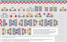
*rubs chin* getting nearer to a goal, of actually looking at companies, and taking something to them to see what could happen. though few more goals still need to be meet. *looks pumped* YA!
==================
before i forget....
if there is a "cab" i might be able to "tuck" it in at one of the ends. there really would not be any "need" to actually run the main support members through the cab due to cab would be at the end. all that really would matter, is attaching and folding an implement up on each side. that alone would really open things up in possibilities for designing a cab and how to mount it / attach it to the SSTT. though i would imagine a Fixed cab vs a cab that is an actual vehicle. the fix cab would allow everything to be compacted much more tightly. and take up less space / less weight etc...
==================
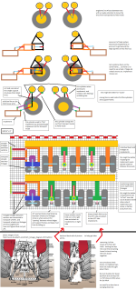
been thinking about all the cylinders... and thinking about a better valve setup. that might allow 3000 PSI on both sides of a double acting cylinder. vs just applying 3000PSI or less to just one side of the cylinder. i would imagine all the valves would be closed center type of valves. perhaps using the "main pressure hyd pressure line" to move the cylinder. and then the other side of cylinder go to atmosphere or low pressure main hyd pipe. then once the cylinder has moved and is positioned, let pressure into the "low pressure" side of the cylinder in. and then return valve to back to center.
i think my mind playing tricks on me, and getting compressed air all mixed up with hyd oil... but i don't know. perhaps fail safe... due to all the hyd lines. and possibility of just a single hyd hose cracking / splitting, etc... and air getting into the entire machine and into everything. would something like above. add a little better stability. so hyd cylinders are not just bouncing all around ((contracting / extending)) like they were made to spring back and forth.
i doubt i really want a tire jumping up and down in a field, causing compaction. even if it might be considered a vibration. from the cylinders with just a very tiny bit of air mixed into the hyd oil...
==================
"air bleed pipe" or function. built into the "lower pressure main hyd pipe" is there away, to mechanically remove air from hyd oil? perhaps get a 5 gallon multi bucket, and just spin the living heck out of it. to a point were air begins to separate from the hyd oil.
i am figuring there is going to be maintenance, and then there is just going to be regular use of machine that will introduce air into the hyd oil. example hooking / unhooking of implements, hooking/unhooking of different sections.
===================
i am kinda edgy on hyd accumulators. more so ones that use compressed gas,or a spring. due to the accumulator in themselves could cause "springy-ness" in hyd cylinders. when the valves get opened up. i guess it would not really matter. if there was some sort of physical mechanical measuring device used. that did not rely on measuring amount of hyd oil going into a cylinder.
=====================
thinking of actual measurement and being able to put a sensor on things, so a computer can figure things out... as in how far a cylinder has extended or not. it would almost have to be a a bar with teeth on it. and then one end would hook to the "rod end" of a cylinder. and this toothed bar would just move back and forth. with a "gear" that rotated a sensor that could be placed into a "housing" of some sorts. to keep all the dust, dirt, rain, bugs, etc... from interfering with things.
the smaller the teeth or rather more teeth per length, i am kinda edge about to a certain point. way to many things to get jammed up. or could cause teeth to break off. if went with larger size teeth and fewer per length. and matched a gear to those teeth. i would imagine both bar and gear would hold up longer. and the how do i want to say it, wear and tear on both gear and toothed bar would become perhaps less. errr the tolerances would not get higher, due to wear and tear would be reduced over longer usage and time.
if the actual electrical sensor what ever it may be, is in an enclosed housing, with some sort of bearing or like separating the gear from the sensor. greasing the track and gear would be possible without ill effects to the sensor.
======================
perhaps a cable bolted down to the "rod end" of the cylinder. and other end of cable wrapped around a pulley or like. naaa... cable would get all jammed up. and be fitting the stupid thing every time cable had to wrap back around itself as it wound back up, or came back off the spool.
perhaps cable attached to a spring? or perhaps block and pulley setup. and then place a sensor on the last pulley between cable being tied off to ROD end, and cable feeding a block and pulley that has a spring or 2.
=====================
hhmmsss.... what about a chain, like a chain saw chain without the cutting edges or bicycle chain. bolt one end to "rod end of cylinder" and the wrap chain around a sproket that is attached to the cylinder. and then place good size spring. to hold the chain tight. and put sensor on the sprocket.
thinking about, a chain and sprocket and spring all sound good for "flexibility" of placement of things. but as soon as that chain broke or a pin or bolt got loose. you would be SOL, nothing would be left, not to mention trying to find a position to use a cheater bar or long screw driver or like. to pull the spring to re-attach a chain.
with a toothed bar and gear setup. there would be issues of things "binding up" but even if bar did get bent. as long as the bar and gear still meshed up and still allowed to move freely. i would think it would out last any sort of chain / sprocket / spring setup. and put a little extra code for computer. to figure out min/max distances of cylinder movement via sensors on pressure relief valves for a given cylinder. i would assume there would be some sort of "diagnostic" setup anyhow. that would calibrate things.
======================
pressure sensors, built into a cylinder or rather valve? or put in between valve and cylinder? i really do not want one tire being placed down in the field and it taking all the weight for half the machine. i would want all the wheels to dynamical raise / lower (aka fold in/out) to adjust amount of weight each tire takes. to reduce compaction. and/or do i move sensor to the rim of the wheel and take pressure readings of the air inside of the tire / tube / rim itself.
i am not sure if that would even be beneficial or come out to anything. by reading air tire pressure, due to tires "flex" to some degrees both across the face and the side walls. can a sensor even be made to "sense" air pressure that is down around 10PSI. and barely even fluctuates. it is not like it is "racing" were tires heat up and air inside the tires heat up and expand as well. and not dealing with a huge size off road dump truck like in mining operations. but hhmmsss...
======================
TIRES, is it possible to get away from "longer cylinders" by simply dropping them down to the ground. and just letting the tire move itself from under the machine to a unfolded out position? and then using some sort of pin that is electronic. to locks some tracks or pipe together to keep them from sliding? naaa that be old outdated doings. gotta have the latest craze! though could it allow for less weight. and better structural support? na... folding things backup would be a pain in rump. and then trying to get through wet soggy mushy mud. a cylinder would have to be there. if not to fold / unfold but to push and pull things around. could see a tire getting swallowed up by mud. and tire just waving bye bye for dead as rest of machine went on down the field. if there were cylinders involved more likely wheel might be able to be pulled up and keep the machine going.
======================
swapping over to implements and how they connect....
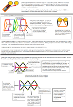
counter balanced left and right side implements. to lower one side, the other side raises up and vice verse. to place them in transport position. they balance themselves out almost. and then something locks the teeter totter frame from swinging.
================
why not... lets just let the entire machine just roll right over on its back. were the transport wheels are. *coughs* boy... i doubt that would go over well. with the first SSTT (sideways snake train tractor) rolls down a hill across a road through some houses and continues to roll till it finally comes to a stop in some gulley or creek or river... and taking everything within a 100 feet plus path of it.
==============
EDIT: last moment thoughts... if the main structural frame. = a bunch of pipes all formed into a frame. would it be beneficial. to have a hyd oil for cylinders, and then another hyd line with a different type of oil in it. for hyd wheel motors. or perhaps going with electrical wheel motors. though i am skiddish about trying to place high voltage current through the linkages / couplers that would go between sections. almost seems like asking for accidents.
===============
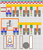
i guess it be time to end this post. and see about getting something going on a grid layout and see if everything could fit in a 8 feet by 20, or 40, or 60 feet long lengths.
