new tractor idea possibly....

   / new tractor idea possibly....
  • Thread Starter
#151  
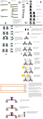
still having problems with the transport wheels. that do 90 degree rotation to go between field mode to transport mode and vice vs.

been thinking along the lines of not expanding / contracting the transport wheels in and out. (from 4 feet to 8 feet) but rather the linkages between SSTT (sideways snake train tractor) and implements. doing something with those linkages. it would be just moving one set of cylinders from the transport wheels over to the implement linkages. at least i would like to think so. and transport wheels would just need to raise and lower straight up and down...

problem at moment though is how to "push" the linkages out. effectively i really do not need to drop them down. due to transports wheels lift up... errr allow entire machine to lower (implements, larger AG / R1 tires, tracks for field mode, main frame / spine of the SSTT, etc...) when entire machine lowers. i need to get the implements far enough out. so when they fold down. they do not catch the transport wheels.

without actual 3D model. i am not sure "how far" the actual implements would need to slide out before unfolding. to allow for weight distribution to happen. when the larger AG / R1, or tracks are placed down and moved side to side. to re-distribute the weight in field. do they need to expand out another 1 foot, 2 feet, 3 feet, up to say i would say guessing 5 feet max....

the transport wheels only move up and down, and most likely have a 360 joint on them. or 180 degree rotation possibilty. ok maybe not 180 but maybe... 170 degree rotation. for when transport wheels are placed into "grain wagon fail safe mode"

hhmmmsss...
 
   / new tractor idea possibly....
  • Thread Starter
#152  
out of one fire and into another fire....

boggen new tractor idea135.png

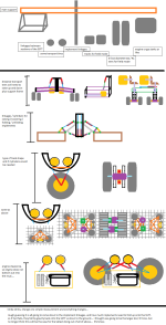
re did linkages for implement doings... and running into some problems with the transport wheels. in how to raise / lower them. along with rotating them... and were to place the hyd or electrical motor.

==================
getting late, so before i forgot... a double rack and pinion. (hopefully correct name) and having 8 individual wheel sets vs 4. to control rotation over 360 joint.

===================
on a different subject before i forget. using a single sheet of metal. and a more likely custom metal break. to make multi pipes with a seam clear down the center of each pipe. and single sheet is never cut to make all the pipes.

quickly looking at a couple youtube videos of how pipes are made. i am wondering how much a custom mold would cost. or seeing about instead of how pipes are shown in the videos as being horizontal as the liquid metal is poured in. perhaps vertically and vibration, to create a much more complex main frame support setup... hhmmssss viscosity and air bubbles and just dealing with concrete :/ not sure about that....

i get a tad un-easy seeing all the sharp 90's and sudden change in direction, seen in many hydraulics fittings and valves. was thinking if a main frame could be some how "casted" and then a few hole drills were needed. might achieve wanted goals. though i would imagine at an expense :/ to achieve a smaller main frame (spine) for the SSTT. and get cooling that would be needed. for hyd and engines and routing hyd fluid were needed...

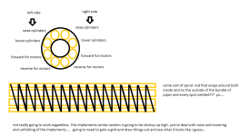
also been thinking of wanting to "warm" up all the hyd oil to operating temperature quickly and efficiently. perhaps a kinda of a spiral metal in shape of a spring running length of a section. and a row of pipes welded around the outside and then into the inside of the spring shape. kinda thinking along some of the rebar setups i have seen for cylinder shape columns... that would later get concrete poured around them. perhaps one more spring shape put in the center. and then a solid bar place in the center perhaps for that last additional support

naa... not need round. but more of a rectangular shape would more likely be more beneficial...

===================
instead of the typical... single hyd pump. feeding pressurized hyd oil. clear through a system. i am thinking of a couple hyd pumps as bare min. all regular hyd valves that goto cylinders. have 2 inlets for pressurized hyd oil, 1 outlet for low pressurized oil, 1 outlet for rod end of cylinder, and 1 for cylinder end of the hyd cylinder.

thinking is if there is a major hyd oil leak. half the system would be down. but still keep the other half operational. well it may not be operational to actually do field work. but enough to stop and get things fixed. before things get completely destroyed. also act as fail safe in transport mode. and keeping some driver, from getting there head torn off, do to a sudden leak in hydraulics. causes a cylinder to let an implement fall down. the double pump and pipes i would like to think as a fail safe.
 
   / new tractor idea possibly....
  • Thread Starter
#153  
ran across some links that might be interest to others...

sizing tractors to implements or vice vs.
http://bsesrv214.bse.vt.edu/Grisso/Papers/06-156.pdf
http://www.caes.uga.edu/departments/bae/extension/pubs/documents/farm tractor.pdf
Publications | Biological & Agricultural Engineering Extension Program at CAES | UGA
Match Implement Size to Tractor to Save Fuel - eXtension
Department of Applied Economics
farmdoc : FAST Tool
http://tractortestlab.unl.edu/publications.htm
http://archive.lib.msu.edu/DMC/Ag. Ext. 2007-Chelsie/PDF/e1152.pdf

website listings for manufacturers of tractors.
Tractors

image caught my eye in one of the google image searches. for dealing with turning..
SUR TRAC Track Kit

=====================
one of the things that grab my attention on tractor sizing links. is notation for potato hilling. and next thought was regular old tillers, walk behinds to self propelled walk behind tillers. and making sure the "tines" turn in the correct direction. with the SSTT being able to have implements on both sides of it. or rather front and back when in field mode. perhaps putting a tiller on the front of the SSTT and getting it to turn in correct direction. so the tiller itself "pulls" the SSTT through the field. vs relying on the wheels / tracks pulling / push the SSTT through the field. then on rear end (in field mode) put tines only were needed to deal with tire tracks, and then go right into the "shaper" / mold for the hills... other words, the front tiller really gets down into things (kinda of a first past till) leaving the rear tiller (second pass) to do less work to get down deeper and allow the mold to create the shape of the hills...
 
Last edited:
   / new tractor idea possibly....
  • Thread Starter
#154  
*looks wired* have not had sugar in ages... was not a very bright idea of drinking some cool aid, a little bit before bed time.... :shocked::shocked::shocked::shocked:

boggen new tractor idea136.png

--implement linkages --DONE
--transport tires --DONE
--large AG / R1 tires --DONE
--need to re draw tracks for a triangle vs rhombus shape. most likely use setup to adjust AG/R1 tires but swapping wheels for tracks.

boggen new tractor idea137.png
 
   / new tractor idea possibly....
  • Thread Starter
#155  
RECAP

kinda doing for the SSTT (sideways snake train tractor)

post 140 to current post covers SSTT

boggen new tractor idea138.png

---need to re-look at possibility of folding an implement into 3 different things so it folds over the SSTT like an up side down U.

---re-draw tracks for field mode

---do a quick drawing to see about putting a combine or like header on unit. and see if there is space for rest of a combine to deal with various crops. to either remove corn from cob to beans, to potatoes, to carrots, to wheat, to hay, to other.
 
   / new tractor idea possibly....
  • Thread Starter
#156  
an attempt to figure out how hyd lines and electrical wires might be ran and done...
boggen new tractor idea139.png

at current moment...

i am thinking about a 4 way stacked valves (all electrically controlled) and then a box right beside it, that would hold any fuses, relays, computer chip. "outlet" wire harness connector that would run down to individual sensors on (wheels/tracks, implement linkages, linkages between sections of SSTT, engines, etc..) it would also have a "inlet" and a "outlet" main wire harness plugs. and everything daisy chains down the SSTT the entire 60 feet width or what ever it turns out to be.

both hyd valves and the electronics box. would mount up on the main frame (spine) of the SSTT.

i am not completely confident on "wire harness" plugs between each electronics box. and might prefer a regular electrical conduit approach, and for main power lines an actual physical nut or screw that needs to be undone to remove primary power cable. and then a bread board of pins or something possibly inside the box. for the rest of the wires? na... hhmmss perhaps a regular water proof wire harness connection on outside of the box for the misc sensor / network cables between each electronic box.

on second thought... going to need to wait. to see if SSTT can be redone easily enough to turn from a tillage and planting machine to a harvester type of machine.

==============
quick thought, we have portal able dumpsters. call up some local company and ask for a dumpster to be delivered. and they bring one out. and toss say old shingles into it, trash, or what ever. then call company back up to haul it away.

instead of having "chaser units" running back and forth between harvester and like. perhaps some sort of "bin" that grain crops could go in and when full just drop right off the back off the SSTT. and chaser vehicle just brings an empty bin back and drops it on the SSTT. and then goes and picks up the bin that was dropped in the field. naaa.. i doubt that would fly. be chasing your own tail.
 
   / new tractor idea possibly....
  • Thread Starter
#157  
how do you adjust or add or remove TEE's or WYE's that would be coming off of the 3000PSI hyd pressurized lines and low pressurized hyd lines. more to the point in the field.

better yet. how do you build hyd valve so it can draw hyd oil out of the hyd lines. so there are no hoses. between the main hyd lines, and the valves.

instead of single continuous pipe. is there a "valve block" of multi hyd valves. and on each side, there are 4 connections. that allow for some sort of flange pipe connection? other words instead of using a coupler or a tee fitting or wye fitting, or other like fitting to join multi pipes together. the valve block, becomes the fitting. but it would not join 2 pipes together but rather 8 pipes together. (4 pipes on each side) and then have what ever hyd ports that are needed to go to hyd cylinders and hyd motors...

that sounds "ugly" lots and lots of hyd oil to drain, just to fix a valve.. ok what about this.

you have 4 Wye fittings all created in a single piece of metal. and then use a gasket either on top say a 0-ring around each of the 4 wyes. and then the actual valve block that bolts down on all 4 wyes

dealing with water and air in the hyd system... do the low pressure return lines be placed on above the pressurized hyd oil lines. and the valve block some how connects in between the upper low pressuized line and below high pressurize lines... with relief valves placed to let air to escape upwards and into the low pressurized lines...

water would more likely collect in all the cylinders and motors. so how do you deal with water besides some sort of separator / filter geared for water?

what things can run in a series vs being ran in parallel.

wondering if spool valves would even be wanted for the hyd motors at all. perhaps a different valve type all together, butterfly valve for example.

========================
========================

*rubs chin* heat and expansion / contraction... 60 foot length. i would imagine some sort of "tolerances" would start showing up over the length itself for hyd lines...

hyd hoses might be needed just to get around from expansion and contraction of a metal pipe.

perhaps a mix and match of metal pipe and hyd hoses?
========================
========================

how to account for "flexing" within the main frame (spine) of the SSTT (sideways snake train tractor).
implement linkages, and engine/s mounting on the main frame, and splitting them up between wheels/tracks i would imagine go a long way. but still issue of "transport mode" and transport wheels i would of thought of as being on the far ends....
 
   / new tractor idea possibly....
  • Thread Starter
#158  
been mulling over the main frame (spine) thinking of various shapes, and connecting points.

some problems running into, have been twisting, flexing, along with how to "mount" the various things to the spine.

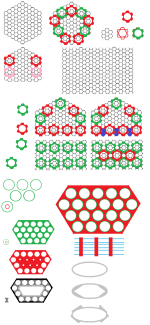
i think i got it narrowed down to a hexagon (6 sided even length shape). and clamp setup. that would allow the spine like your own spin in your back. to slightly flex in all directions pending on clamp used. the problem is, i am not sure about smaller internal structure of the spine. the metal would need to be extremely thin in spots. and i am not sure if the forces placed on the spin would not cause these thinner parts to "buckle" and collapse in on themselves. thicker these thin spots would become heavier everything becomes...

i am not entirely sure about hexagon shape. and have thought about some puzzles. that might work out better. instead of hexagon shape if the internal voids can be maintained to reduce amount of metal needed and in that reduced weight.

i think the clamps would work out decently, to "hold" the hyd lines, and pipes for hyd oil and electrical, air pressurized air for fail safe brakes.

i don't think that much actual welding would be needed for the spine. but rather, the clamps themselves will be the bigger price tag for cutting / drilling / grinding / welding. most of the spine i would like to think would be fairly easily automated during its creation and just some simple molds might be needed.

rust.... that is a big one. that does have me worried. more so with flexing of the spine. there will be really no way to "grease" or put lubrication into the spine. wait a minute YA. the clamps!! but how do you force grease into those long lengths.... not to thrilled about idea of putting down sheets of plastic. to let a oil or lubrication or like work its way through the spine... i suppose a thin as possible sheet metal bent to needed shape and act like a "sleeve" errr shirt sleeve... that goes over the spine. some how slide into groves of the clamps?!?
 
   / new tractor idea possibly....
  • Thread Starter
#159  
boggen new tractor idea141.png

i can already see it, some bozo, making a long submarine or torpedo shape main frame (spine) of the SSTT. were the engine or engines are created within the casted metal frame. i guess it might more look like a single rear axle on a truck. but the differential housing being elongated along the axles. to house 1 or 2 engines, and some hyd pumps. and then the wheel hubs being brought back to the ends some, to handle the linkages between sections. and some flatted out areas to attach the implement linkages, wheels / tracks.

and say a good portion of the entire casting has to be re-done i want to say a good 75 to 85%, because some bozo with money just burning a hole in his pocket jumped the gun. and kissing the budget goodbye.

guessing the brackets errr holes placed into each portion that makes up this thing along with the bolts. would rip out first time any sort of physical pulling happen just at the ends or perhaps just at the center. and just begins bending the entire main frame (spine) of the SSTT. to point it ruins the spine.
 
   / new tractor idea possibly....
  • Thread Starter
#160  
going to start contacting some companies and see what can happen. jumping the gun a little bit, without getting everything into a actual presentable doings. but what the hay!

called and emailed Caterpillar yesterday. being there in my own back yard per say. and waiting for a telephone/email back.

will be contacting John Deere tomorrow (friday), due to next nearest company. and would most likely require a half to full day trip (all around) though i am guessing, it is going to require an actual trip to there headquarters, to get anything moving and turning.

been looking at other companies websites and trying to get some idea of there various locations, head quarters, R&D, foundries, assembly plants. and all others require 2 to 3 day trip by vehicle to get to them. and going to hold off from contacting the further out companies.

===================
been thinking of technical skills of what would be needed. to pull the SSTT off.

computer programer, with skills to program some chips. been thinking of robots / robot chips, that a few companies out there have dedicated the entire company to, in just making chips, software to program, etc... to program things, but not sure if that would actually work. and going to assume some sort of Proprietary software / chips and software... guessing 1 manager, with a small crew to fall back on. to write various routines.

some sort of structural engineer. perhaps someone with back ground with self standing cranes that almost mount directly to a multi story building. or perhaps engineer with background in multi story buildings. better yet someone with background in "bridges" more to the point 1 to 3 people, that could possibly take on the SSTT spine. each one taking on a different design that more suits there knowledge base / experience.

someone that has worked with "tracks" and wheels, and already has good knowledge of stresses / forces the frames and supports and wheels, etc... would need to take. and at same time to keep build up of mud, dust, etc... from destroying things.

someone that is a "tire person" perhaps someone working directly with various tire companies directly. or perhaps bringing in a person directly from a tire company, into the fold. both for AG / R1 tires, to transport tires. and finding both tread and sizes for tires. to deal with transport mode, and field mode for the SSTT, i would imagine, 2 friends that are really dug into "soil" composition. and how various tread patterns and weight come into play. to get the most bite into the soil. going to assume both would work into the "rubber tracks" and tires. for correct tread pattern, thickness of rubber, how bands, etc... would be done. and then narrowing down what might already be out there on the market that might be used to off set price of custom made doings vs what is already out there.

someone that is familiar and hardcore about different types of engines, just not the standard engines in cars/trucks/tractors. but perhaps air plane engines, to other... the physical dimensions of were an engine/engines could be placed has me *cringing* some, vs what is out there on the market. guessing some sort of engine type, getting re-purposed for the SSTT. and either down sized or getting all the new technology added to it, to bring it up to current age doings.

fluid dynamics person. more so with knowledge in hyd pumps/motors, hyd cylinders, and valves. and more to the point what it takes to actually, cut, drill, grind, etc... to make the various pieces. at moment, i am not to thrilled, of what i have seen for internal passages within the various components. it makes me think someone just hodge podge, things together, without taking currents of the hyd oil into consideration. and causing excess heat build up and placing extra stress on components in other areas, i am not sure things could be pulled off. without counting them pennies errr degrees of heat build up. and reducing them as much as possible within reason. to allow for hyd oil cooling to be reduced.

guessing the 3D modeling staff, is upto par in there areas. but some sort of need. to bring in or get them in touch or rather to the point working with others, to cover areas that the 3D staff is not up to par with, on a case by case / individual by individual basis...

==================
i have been pressing the "implements" off to the side in all my thoughts up to this point. with primary focus on the SSTT (sideways snake train tractor) every implement is going to be different. and at moment, not sure how to even handle implements. good portion most likely i have not really taken time to really sink any thoughts into them. and have for most part, just took them as a no brainier. but i know that is just asking for a train wreck to happen. i am actually more worried about the "conversion" between tillage (plows, discs, rippers, etc..) seeders/planters. but more so worried about switching over to the harvesting.

tillage for most part has one side of things, but harvesting...brings in need for bins to hold the crop, along with moving the crop around the SSTT to get to the bins. and seeders/planters kinda being in the "middle of the 2" (tillage and harvesting).

because of such a wide range of what might attach to the SSTT. at moment. i am more inclined to see about getting some 3D models / variations going just of the SSTT. and then build upon them. to see how various things would attach. and redesigning things that would allow the switching easier overall. it is the full concept of more likely being able to attach things on both the front and rear of the SSTT. vs current age tractors and harvesters that only attach to the rear or front of the machine. without a major few days of changing things over to get the more complex things setup...

=============
with above stated, i am more inclined to settle with less expertise at the 3D staff. for initial stages of R&D / concept / design. and then as things get narrowed down. bring in the knowledge if needed, to fine tune things. and making sure things work like suppose to. man, that did not come out right. i should say more "wild ideas and everything goes" during initial stages, and as things get re-designed, and narrowing things down to a final design, having others do a peer review perhaps to look things back over and to help fine tune things.

==============

*rubs chin* start off with a couple folks, or perhaps a large team of folks, and only use a couple folks at a time to hit specific things for the SSTT. for initial concept, to obtain generic data set of "weight, forces, stresses, etc..." and leaving things completely open. during the initial concept. and as pieces / portions get done. getting the various folks to begin to work with each other. so things can be taken into account.

i have absolutely no idea on any sort of time frame on anything so just purely guessing. say 3 to 4 weeks, then stretched out to 3 months. to get past initial design. to point of working SSTT machine. with some basic implements. enough to throw into a simulator.

man.... the part i do not like is the implements / harvester stage. so many "small goals" each goal being for a different type of implement. so many multi tasking doings. and working on different implements at any one time... this alone has me some what worried. and folks falling back. to those that did initial 3D model/s of the SSTT. every implement is going to need to be cross referenced and double / triple checked. any time a small design change happens with the SSTT machine itself.

i take above back. been awhile, since dealing with the various software packages out there. that deal with different revisions and sharing of files between team members. i would imagine and descent size R&D department already has a IT staff on the ball. and things already in place. and various software packages working together. between 3D modeling, animation, simulator, revision software, hierarchy / control / permission software...

=============
question/s is were would i fit in, into the team. and have companies actually looked into this already, but scrubbed the idea for this or that unknown reason/s...

=============

posting before i loose everything...
 
 
Top