new tractor idea possibly....

   / new tractor idea possibly....
  • Thread Starter
#201  
transport wheels.... eletrical wheel hub motor, brakes, suspension, and rotation of wheel in one small package.
https://www.youtube.com/watch?v=8tLQ2-yKT4Y
to above video, redoing suspension, a little bit to raise and lower wheels possibly.
also to above video, tire pressure gauge... never thought about a wireless sensor. that has some sort of "motion" generator in it. to produce electricity. (as the generator / sensor rotates around the wheel, the rotation itself causes generator to spin)

ok, finally hit me, seeing the video, it finally hit me. hyd motor vs electrical motors. and that is the internal parts. or rather. a hyd motor, is going to require some sort of cylinders and rods to create the rotation force. vs a eletrical motor. only has 1 single rotational part.

i take above back geared typed of hyd motors / hyd pumps. less moving parts = less wear and tear long term. but in order to get to something advanced enough in hyd motors to adjust RPM's and/or Torque there would be a need for a good amount of additional mechanical parts that move...

================
hit wikipedia, for electrical motors, and found my way onto, relays, and never even thought about use of them. and used like a pressurize relief valve in hydraulics. so much amps / volts and a relay begins opening or closing the circuit some, to change amount of amps / volts going to the motor.

================
do not have a slightest idea about math / formulas / equations, to even to begin to roughly size a motor based, on wire gauge, and loops in a winding/coil. to produce either RPM's and/or torque.

the other part is.... multi phase wiring.... and can i get past the DC to A/C conversion at the generator. awe..... wire gauge and distance being ran...

================
other issue, is water jacket, if electrical motor needs cooling. and then emergency brake / fail safe brake. and then some sort of cover for the brakes themselves.
 
   / new tractor idea possibly....
  • Thread Starter
#202  
110HP wheel motor
https://www.youtube.com/watch?v=ZnhmND1KQ_4

DIY / water cooling for a wheel motor
https://www.youtube.com/watch?v=C0aRmSR4a8o

wheel motor actually spinning, and changing RPMs i think
https://www.youtube.com/watch?v=YaIwTTpztaI&feature=endscreen&NR=1

guessing some sort of memory product made into a wheel for the army?
got to thinking regular 4 foot diameter AG/R1 tractor tire. and able to place more rubber to the surface.
New Tire Technology Used on a Pick Up Truck - YouTube

yikes, long 135 page pdf. going over various aspects of a squirrel cage motor.
http://www05.abb.com/global/scot/scot259.nsf/veritydisplay/bf88560fb1b0335cc2256fc6003e4e05/$file/motor%20guide%20gb%2002_2005.pdf

*gets lost, in all the specs and configurations...*
ABB Motors and Generators

little funky, it is a website built into a program. and there is some "wait time" between downloading stuff, and what information becomes available in a PDF file.)
GE US English Catalogs
GE Energy - Motors Overview

wheel motor company
PML - Innovators in Motion. Manufacturers of Flat motors, pancake motors, wheelmotors, joysticks, drives and controls.
 
   / new tractor idea possibly....
  • Thread Starter
#203  
been battling with autodesk for last couple days. and not really much to show for it.

been trying to find the groove per say. of working through things and thinking a few steps ahead, in how to draw something up. and finding some things do and do not work so well. resulting in restarting from scratch a few times. the constraints of autodesk is the big one, and then dimensions linked to constraints. just makes things into garbage after so many edits.... do not pull a dimension off before changing another value and i end up with foo bar...

below is finally something that did not result in geometry not looking like a rag dog, after the puppies had it for a few minutes...

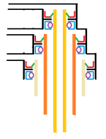
diagram created with autodesk inventor student edition.
sstt1.png

dual transport wheels
---tire and rim lip (if you could even call it that, (quick and dirty))
---inner rim, with magnets on it. for an electrical motor. (have not figured out how to do elliptical or wavy "coils" of wire just yet) and hopefully some room for some brakes
---T shape support structure.
---axle though at moment showing as a single axle vs 2 half axles. not really sure how much room an electrical motor will take up. and it may come down to placing motor in one wheel, and brakes in the other wheel.


==============
office 2010 excel installed, so hopefully now will be able to go through some more tutorials that requires excel usage.
updated satellite, so hopefully should be good to go, even if i do go over my current plan max megabytes.
 
   / new tractor idea possibly.... #204  
Looks like you are making good progress. Inventor and other solid modeling software has a big learning curve. Hang in there!
 
   / new tractor idea possibly.... #205  
been battling with autodesk for last couple days. and not really much to show for it.

been trying to find the groove per say. of working through things and thinking a few steps ahead, in how to draw something up. and finding some things do and do not work so well. resulting in restarting from scratch a few times. the constraints of autodesk is the big one, and then dimensions linked to constraints. just makes things into garbage after so many edits.... do not pull a dimension off before changing another value and i end up with foo bar...

below is finally something that did not result in geometry not looking like a rag dog, after the puppies had it for a few minutes...

diagram created with autodesk inventor student edition.
View attachment 283651

dual transport wheels
---tire and rim lip (if you could even call it that, (quick and dirty))
---inner rim, with magnets on it. for an electrical motor. (have not figured out how to do elliptical or wavy "coils" of wire just yet) and hopefully some room for some brakes
---T shape support structure.
---axle though at moment showing as a single axle vs 2 half axles. not really sure how much room an electrical motor will take up. and it may come down to placing motor in one wheel, and brakes in the other wheel.


==============
office 2010 excel installed, so hopefully now will be able to go through some more tutorials that requires excel usage.
updated satellite, so hopefully should be good to go, even if i do go over my current plan max megabytes.


Ryan on the elec. wheels it is DC voltage and for brakes reverse the voltage. Also the DC voltage is pulsed to increase the speed so voltage remains constant.
ken
 
   / new tractor idea possibly....
  • Thread Starter
#206  
Looks like you are making good progress. Inventor and other solid modeling software has a big learning curve. Hang in there!
*shrugs* learning curve really not that bad, it is finding the limits, that gets a little frustrating. and in that thx for encouragement!

Ryan on the elec. wheels it is DC voltage and for brakes reverse the voltage. Also the DC voltage is pulsed to increase the speed so voltage remains constant.
ken

i do not think i am going to get away from. having some sort of brakes, disc to drum, wet or dry type. for fail safe backup. if electrical goes out. (example turning machine off while parked on a hill) there is going to need be for something. to hold the machine from rolling down the hill. and one of things i did pickup from looking at trains, is once RPM's get so low, breaking with motors becomes less. and need to rely on a secondary mechanical braking is necessary.

the post 202, i did catch some of the notation of changing the mufti wave forms of the electrical single. being sent to the coils of an electrical motor. my brain got a bit overloaded, by all the blah blah, vs needing the cut and dry form, of example of math. while voltage might stay the same, the AMP's do change. it is one or the other. amps or volts that change, and then pulse or wave pattern of the electrical single. or less i am missing something?

just kinda passed on electrical motors, for time being before really digging into them. need to hit some more tutorials, and figure out a way to get inventor to draw a oval shape coil. or waved shaped coils.

====================

yesterday, backed away form inventor, to look up rotation seals, to deal with water/antifreeze (coolant) and air for (fail safe brakes) and getting inlet/outlet for fluid and then air through the 360 joint for transport wheels.

----the shaft or make that pipes going through the 360 joint, will not be rotating at any sort of RPM (revolutions per minute) but rather short degrees of 0 to 360 degrees. and rarely making a full rotation. that alone puts limits of what seals can be used. with many seal types relying on some RPM to create an actual seal.

----PSI (pressure) both for air, and coolant. is another issue, not just regular pressure during normal operation, but also when coolant over heats and boils over. and max relief valve setting for compressed air.

----temperature for coolant fluid.

----diameter of seals, and needing...
--------electrical wiring, and/or frame
--------1 to hold back fluid
--------(coolant)
--------1 to hold back fluid on both sides of the seal
--------(coolant)
--------1 to hold back fluid on one side, compressed air on other side of seal
--------(fail safe for breaks)
--------1 to hold back compressed air
--------electrical wiring, and/or frame

----with above, then being limited to "height" or length. either above or below the 360 joint.

---other issue, is some seals are made for single direction rotation (clockwise or counter clockwise rotation) and not bi-directional rotation.

================
other issue, with coolant, is controlling how much GPM of coolant goes were. with hyd oil, and hyd motors, there was valves already in place. to control amount of fluid and were it went. but with water/antifreeze mix like coolant. there is nothing there. by default, or less i wanted to make a mile long path for coolant to circulate through. or place some sort of small size pumps or valving to help control how much coolant goes were. if nothing extra was put in, the result would be the path of least resistance would happen. and all coolant would go through path of least resistance, causing everything else to over heat. and tossing a bigger pump on and calling it good enough. does not cut it either.

other words, complexity of hyd motors vs electrical motors. electrical motors just got more complex, and needing a control system just to deal with coolant.

how the control system is put into place may have a very distinct advantage or dis-advantage. to min / max pressure and the 360 joint, and in that the seals.

===============
alright getting back to seals.... links....

search terms.... rotary, rotation, swivel, seal, bearing, mechanical, hydraulic, coolant, compressed air, joint
mixing and matching terms, seems about only way to get results back.

pictures of various seal types
Seal Types

manufacture of seals
Sealing Solutions | The Garlock family of companies

looks like some sort of school / text book, info for seals ((links to other companies at bottom left of pages of seals))
Seals

another description of types of seals
Dynamic Seals

goes over seal types as well.
http://machining.grundfos.com/media/16602/shaftseal_chapter2.pdf

one of my side tracks, to look at "unions" or "couplers" or "swivel connections" for dealing with 360 joint
Rotating Swivels - Rotary Swivels - Rotary Couplings - Rotary Joints - Rotary Unions

i am still reading the 400 plus pages of this pdf covering multiple seal types.
http://www.parker.com/literature/Engineered Polymer Systems/5350.pdf

================
*rubs eyes*, knocks the skull. yep still there.

page 205 couple pages for requesting help in selecting a seal type.
http://www.parker.com/literature/Engineered Polymer Systems/5350.pdf

one long PDF, but reminds me of "text books" in school. explanation and math, and design. all wrapped into one, without any extra blah.

more info on seals...
http://www.parker.com/literature/Engineered Polymer Systems/5340.pdf

================
getting electrical wires through the 360 joint...

up to this point, been thinking about having electrical wires, run up through the very center of the 360 joint, but i think, i am going to switch that over to a "pancake" design. vs joystick up to this point. just need something with better long lasting brushes or multi brush setup. for U-ring shaped metal contacts... cost will be higher for pancake vs joystick design. but may give me those few 1/8 of an inch that might be needed.

back to inventor. to see what happens...

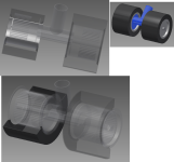
below quick and dirty. of reducing seals / bearings down to 3 to deal with coolant and compressed air.
360 fluid joint.png
 
   / new tractor idea possibly....
  • Thread Starter
#207  
:/ need to come up with a better way to pancake the electrical wires, going through the 360 joint.

perhaps a U channel, and then an upside down U channel of copper or like. and let them rub against each other. with some springs located every so often around the U channel circle.

perhaps do something like various oil seals and like do. and form a single flat bar wrapped around a circle. with a spring on one side. to cause the circle of metal to want to get tighter around the center. and then do anther flat bar and spring. but this time put a spring to cause the flat bar to want to get "larger" in diameter. that actually might work.

problem is. man, that metal bar might get rather heavy, and rather thick... to handle the AMP's and/or Volts going through it. hhmmsss *light bulb*
 
   / new tractor idea possibly.... #208  
:/ need to come up with a better way to pancake the electrical wires, going through the 360 joint.

perhaps a U channel, and then an upside down U channel of copper or like. and let them rub against each other. with some springs located every so often around the U channel circle.

perhaps do something like various oil seals and like do. and form a single flat bar wrapped around a circle. with a spring on one side. to cause the circle of metal to want to get tighter around the center. and then do anther flat bar and spring. but this time put a spring to cause the flat bar to want to get "larger" in diameter. that actually might work.

problem is. man, that metal bar might get rather heavy, and rather thick... to handle the AMP's and/or Volts going through it. hhmmsss *light bulb*

Does the 360 joint have a home position? If so then I would just us a cable. Wipers, etc get very complicated and have reliability issues.
 
   / new tractor idea possibly....
  • Thread Starter
#209  
the 360 joint has taken a life of its own....

after getting fed up with constraints. i backed down, to just using parallel and perpendicular restraints. and using variable names, as dimensions are entered. slow going, but so far AWE! *looks relieved* less head aches...

was not really liking how far the last diagram in post 206, was poking up into the air. above the 360 joint. little bit different design. with 6 channels of bearings, and 6 seals. but looking much better and possibly a little bit more compact. still working on the new design with 2 Fluids (1 inlet / 1 outlet) and 1 compressed air.

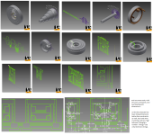
various random diagrams. as i attempt to learn autodesk, and get something done for the 360 joint.

360 overview.png

p.s. going to need to get a new keyboard, with higher raised bumps for F and J keys i keep sliding right over the bumps with fingers... :/
 
   / new tractor idea possibly....
  • Thread Starter
#210  
Does the 360 joint have a home position? If so then I would just us a cable. Wipers, etc get very complicated and have reliability issues.

cable. i don't know about that, though what you call wipers, maybe something completely different than what i am thinking they are, if ya ever had a toy train set, or played with them wired remote control cars that rain on there own powered track, to just dealing with brushes for regular electrical motors for power tools. need something that will last both from plain old corrosion build up, but also wipers, or a brush, or like. needs some "wear and tear" built into them. so things do not grove things out and cut right through things....

the hinges or fasteners also take a good amount of abuse that hold things. trying my best to stay away from any sort of "sharp" bending of metal strips. or less extra thickness is placed in.
 
 
Top