new tractor idea possibly....

   / new tractor idea possibly.... #211  
the 360 joint has taken a life of its own....

after getting fed up with constraints. i backed down, to just using parallel and perpendicular restraints. and using variable names, as dimensions are entered. slow going, but so far AWE! *looks relieved* less head aches...

was not really liking how far the last diagram in post 206, was poking up into the air. above the 360 joint. little bit different design. with 6 channels of bearings, and 6 seals. but looking much better and possibly a little bit more compact. still working on the new design with 2 Fluids (1 inlet / 1 outlet) and 1 compressed air.

various random diagrams. as i attempt to learn autodesk, and get something done for the 360 joint.

View attachment 284450

p.s. going to need to get a new keyboard, with higher raised bumps for F and J keys i keep sliding right over the bumps with fingers... :/

Nice drawings! Yes that looks like "wipers" or brushes. I would seriously avoid using them unless absolutely necessary. I think a cable will be much more reliable and robust out in the mud... just my 2 cents. :2cents::2cents:
 
   / new tractor idea possibly.... #212  
Okay more cents... :2cents:

In my opinion you should design your equipment around already available and proven components. No need to reinvent the wheel as they say. My point is directed to the end goal of building a working prototype.

No need to spend large amounts of time developing individual components. Develop the system as a whole first using available components. Only custom design stuff when absolutely necessary. If the prototype is put into production... THEN all the custom parts, etc will be designed by a team of engineer and suppliers of those parts and pieces.

Work from macro to micro with the design... again just MY opinion! :D I'm very impressed with your efforts! Keep up the good work! :thumbsup:
 
   / new tractor idea possibly....
  • Thread Starter
#213  
fully here ya PapaPerk, of using what is already out there on the market already. and only custom make, what needs to be custom made.

as far as "pre-made" stuff, that is what i am sorely lacking at moment. are resources to fall back on to. that i can just open file, pull dimensions and drop into a assembly of parts. internet searches, so far have not really been that great. parts here and there, of completely random stuff. does not do me much good.

was hoping i might be able to find specifications on websites, or a form to fill out even, to connect to various companies database servers / computers, that had "pre-made" parts. that i could pull up into inventor or some other 3D program. or order some sort of DVD disc with parts on them. but so far, i have not found anything.

i just can't go to some local parts store and open up some part books, not all the info is there for full dimensions. to even create a 3D diagram of a given part.

most likely going to need to pick up the old phone and start calling around.

================
ya got me lost on cable.

or less ya mean, just placing a cable right around the 360 joint. and make sure the 360 joint does not ever do a full 360 in either direction. or risk pulling the cable apart. that i am trying to avoid completely. were cable by passes the 360 joint and does not allow for full 360 degree rotations.
 
   / new tractor idea possibly....
  • Thread Starter
#214  
360 overview 2.png

16 to 20 hours shot.... on that idea. awe well.... time to try again on a different fluid / air going through 360 joint.

problem, to large of of overall diameter once done. it gave me a few ideas...

below might work out nicely, would imagine, there already some sort of ball bearing and seal combo i might be able to slide right in. without to much fuss, if not, should be able to find seal that would fit in, along with some ball bearings.


=====================
googled "electrical rotary connector" clicked over on images. and wealth of pictures showed up right away.

thinking about a male or female connectors on top of the "electrical rotary connector" and then a male or female connector on bottom of the "electrical rotary connector". for quick replacement.

did a search for "electrical rotary connector 30amp" and got a few hits back. tried 50amp and 60amp and did not get any were fast.

=====================
i saw key words "fluid rotary union" in a pdf file...

and heart skipped a beat.... *chuckles* figures after spending a 3 to 4 days so far on 360 joint just for fluid / air.

======================
a search for "brushes wipers electric -windshield" came upon this page, not exactly what i was thinking but close enough.
http://store.eurtonelectric.com/specialshapes.aspx
 
   / new tractor idea possibly....
  • Thread Starter
#215  
4 way 8 banger 4 cylinders 8 wheels 2 pipes and rods1.png

starting to get the hang of things better.

scissors like a scissor lift might use is no good. forgot all about. how scissors change sizes as the extend up and down. was more hoping for "fixed" points. and avoid and sort of track setup.

scissors.png
 
Last edited:
   / new tractor idea possibly....
  • Thread Starter
#216  
figured i would go a searching for ways folks have already done as far as limited how much something could hinge. via block stops or like. and came across Heavy / ODC Transport in India interesting pictures. plus a spread sheet of companies in heavy transport businesses and how many things they sold.

TIP: click on below link, then click on the image to see a GIF animation of a locking cylinder. looks nice and simple, and for transport wheels holding would be critical. was thinking about something to add around the rod or something to lock everything in position. hhmmsss
Lock-on-Extend :: PFA Incorporated

not really liking the screw / thread locking setup. sounds like just asking for trouble of threads catching and binding up.
Locking cylinder - Cottrell, Inc.
6575678-0-display.jpg


don't know. get a wheel caught up in a good rut, and mud just sucking wheel down further.... will removing the diameter of the rod some for a locking setup. hold long term or cause problems with rod bending.
A traning of self-locking hydraulic cylinder-Hydraulic Cylinder
6_111017112132_1.gif

6_111017112253_1.gif


=================

boy did i get myself i trouble...
goto google type in site: Miniature Construction World - Homepage
(site: then the website address) click search
click over on images.
lots of pictures!!!

highlights from above site....

((check site out itself good paragraphs for every picture!))

Miniature Construction World - Scheuerle SPMT Set
IMG_6779.jpg

IMG_6773.jpg


Miniature Construction World - Scheuerle InterCombi with Volvo FH16 - Van der Meijden
IMG_0757.jpg

IMG_0658.jpg


if it was only 360 degrees... turning...
Miniature Construction World - MAN TGX XXL SLT with Goldhofer STZ-H6 Semi-Trailer
IMG_7395.jpg


Miniature Construction World - Title
IMG_3411.jpg

IMG_3408.jpg

IMG_3407m.jpg

it might be a trailer, with frame under neath. and as wheels raise with hyd cylinder excavator comes off the ground. but looks very promising.
IMG_3436.jpg


did not catch this till i almost closed out of it....
2 trailers. and then caring a heavy object between them.
Miniature Construction World - MAN TGX XXL 8x4 with Goldhofer 16-axle Girder Trailer
IMG_8446.jpg


never really thought about it, but triangle piece for allowing longer lengths....
Miniature Construction World - Hitachi Zaxis 350LCK Tracked Excavator
IMG_1437.jpg


long since past idea for transport wheels. just takes up to much room. for a single axle. on being able to rotate wheels all the way around between transport mode and field mode.
Miniature Construction World - MAN TGX 6x2 with Nooteboom 3XL Teletrailer
IMG_6369.jpg

IMG_6366.jpg


again. to much room taken up to spin wheels around between transport mode and field mode.
Miniature Construction World - MAN TGX with LTM11200 Boom Transporter
IMG_5338.jpg

IMG_5368.jpg


been thinking something along these lines, as i was messing with autodesk inventor student edition, and last set of transport wheels i posted to this thread for the lower frame. (partial reason for ball socket joints on end of cylinders. to deal with (row crop spacing of tires)
Miniature Construction World - Kenworth T908 Prime Mover with Drake 8x4 Swingwing Trailer and 8x2 Dolly
IMG_9583.jpg

IMG_9619.jpg

IMG_9621m.jpg

IMG_9622m.jpg


=============
off to see what i can draw up with the funky trailer wheels from above.
 
   / new tractor idea possibly....
  • Thread Starter
#217  
getting a tad aggravated, every time i get close to finishing something up, autodesk inventor crashes, or causes computer to lock up tight.

it took me a while, with autodesk to figure out how to create dimensions at an angle vs horizontal or vertical. as soon as i did it, i accidentally grabbed a hold of one of the dots and dragged a few things out of proportion. so was like COOL! so i started to draw up some lines for linkages for transport wheels, to get a better view point of how things would happen. after first couple diagrams. it turned into a "hang man" game. not joking! couple of the diagrams, when moving, looks like someone hanging upside down, with there feet tucked in, and doing sit-ups.

game of hang man linkages.png

without getting to carried, i am able to set so many dimensions and angles, and then leave any were from 1 or 2 dimensions as "unknown" to act like hyd cylinders. and leave angles between lines left alone to act like hinges.

i am stilling having a rough time, of what to go with. more so the "arc" or path that transport wheels make when raising and lowering them.
and then dealing with trying to dimension out right at 8 feet. to deal with being on the road in transport mode, then switching over to field mode.
the other issue is amount of hydraulic cylinders.

been going back and forth. to deal with spacing tires for "row crop" i think i am down to placing a bracket on each side between 2 sets of transport wheels. and then the clamps or brackets that mount up on the SSTT main spine of a frame. making some extra holes there. to adjust wheel spacing. 10 to 20 bolts. if figure 2 bolts per bracket, should not require any other machine, besides a farm jack (4 to 6 foot tall farm jack) to slide things over. and extra thought placed in length of hoses and wires. to allow for wheel spacing and not having to redo them. be kinda like redoing wheel spacers of 6 or 12 wheel current age tractor. well transport wheels could do a min of 90 degree angle turn. may not even need a jack. just a chain binder or like. to help do finial adjustments to align holes up.

so down to how to place cylinders.....

would like to try to keep it down to 1 cylinder per set of transport tires a set = 2 tires aka duals. like a narrow front end tractor set of tires. it would make things that much more simpler to go with 2 cylinders per set of transport wheels. to allow virtually unlimited positioning. problem is complexity....and points of failure raises not doubling but exponential i would think.

off to autodesk inventor. and look at 2 cylinder options. and see about some mockup 3Ds
 
   / new tractor idea possibly....
  • Thread Starter
#218  
hhhmmsss....
not really liking that the wheels stick out almost 10 inches as the wheels raise upwards.

shortening the links reduces how far transport wheels stick out in field mode. but still 7 plus inches.

boggen SSTT transport wheels1.png

:confused2::confused2: rolls off to bed
 
   / new tractor idea possibly....
  • Thread Starter
#219  
not much done today. been fighting autodesk inventor constraints. and taking 1 step forward 3 steps backwards :/

boggen SSTT transport wheels3.png

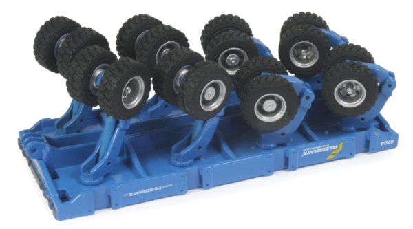
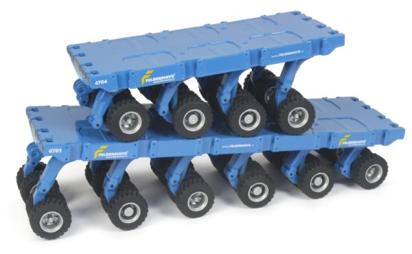
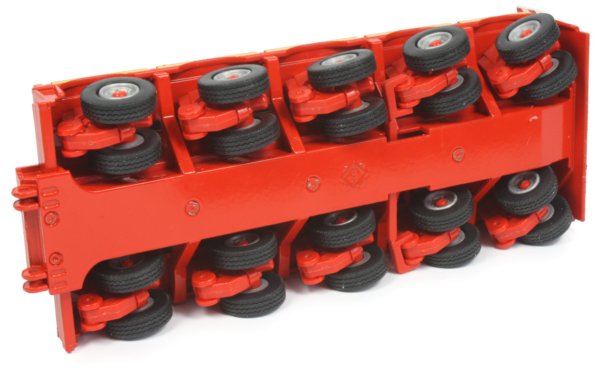
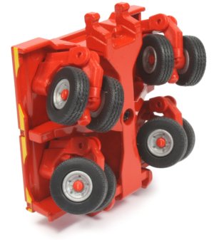
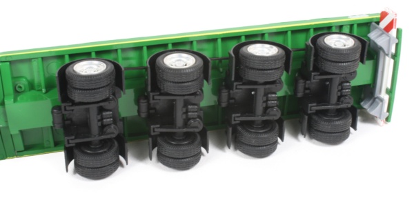
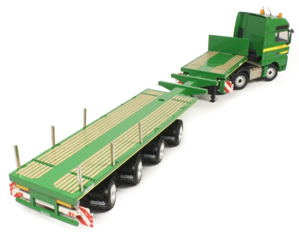
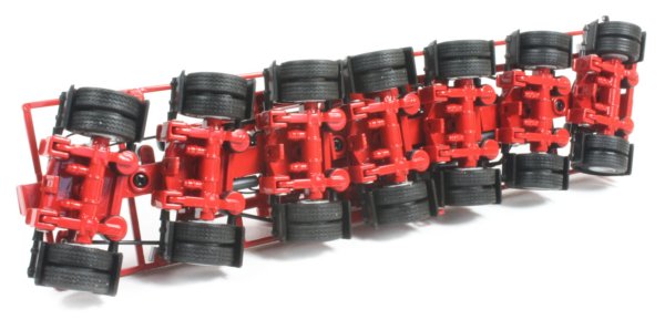
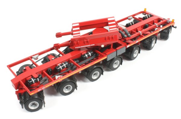
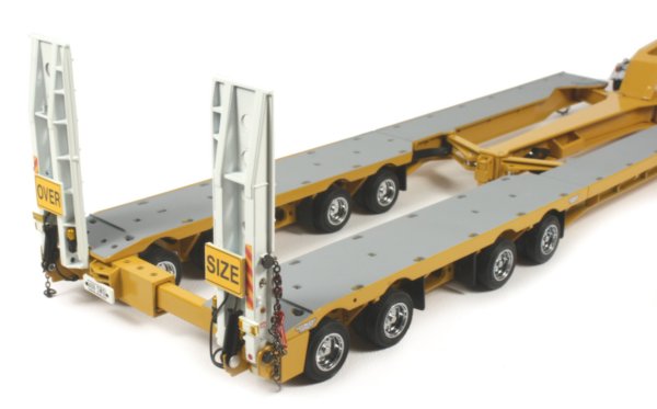
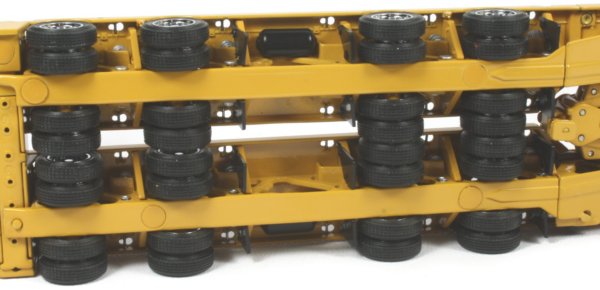
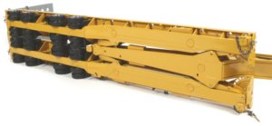
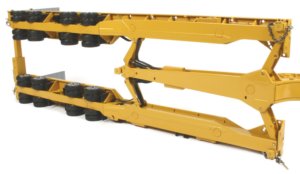
for the transport wheels see last diagram above. thinking of just mounting the cylinder portion of a hyd cylinder. directly to the main frame. so the cylinder is not able to actually freely move in any sort of direction. and lust let the Rod go down and connect to the sub-frame that the transport wheels are connected to.

other solutions for transport wheels in this thread. just causes to much free play. and end up chasing tail around. something bends here, or holes wobble out, pins slightly bend, and things just start falling apart. and binding up on to one another. then the "swing out" of other solutions for transport wheels. is a big problem when it comes implements. more the transport wheels "swing out" further the implement has to be swung out. so the implement does not bind up and come back up on the transport tires, taking both tires and portion of the implement out at the same time.

======================
trying to figure out what might be the best approach to "beef" up things. so the rod of the hyd cylinder does not need to be overly sized diameter up beyond comprehension, let alone $$$. also need to come up with a better solution than using approx 40" inch extend/contract hyd cylinder.

thinking C channel metal bar. with wheels in it, that first come to mind, but i am not about to fight a stinking little wheel. that is catching and tearing things up. on a conveyer belt ok. enough little wheels mass produced. but beefer wheels for the C channel track metal bar for transport wheels... first reaction, is.... see how much explosive it takes or how much needs to be cut out, in order to get things operational and in working order.

i am a little on edge with using a pipe inside of a pipe. not actually a hyd cylinder. but just a pipe inside of a pipe. to help transfer forces between transport wheels and the main frame and vise verses. but with pipe, once you start to get a bend and pipe begins pinching. ya in trouble quickly. on other hand pipe inside of another pipe. allows nice even surface all the way around to absorb and transfer stresses and force from multi directions.

perhaps a I (capital i) or T beam, inside of a C channel beam. and toss some grease zerks in. i would get away from pesky wheels in the track of a C channel. gain strength in 2 different axis (X,Y, and not Z). Z = hyd cylinder itself. if something does begin to bend to pint of pinching. it would most likely cause the C channel beam to open up some. and some relief valves for the hyd cylinder go off. but would most likely still be able to raise and lower the transport wheel. it may be on its final leg. but perhaps enough to get things back to the shop so it can be repaired.

================
I or T beam inside of a C beam, i like it.

but what sort of configuration to put them in, and placing the hyd cylinder into the mix........

off to autodesk inventor.... to hopefully draw something up that is possible.
 
   / new tractor idea possibly....
  • Thread Starter
#220  
just been doodling some for extra frame work to go side by side with hyd cylinders for transport wheels.

boggen SSTT transport wheels4.png

been trying to create 2 C channels that interlock and slide in one another. but having hard time actually drawing it out. i see it in my mind. but so far been unlucky. i think most of the want is more of wanting to learn how to do it in autodesk inventor like a challenge

though looking at triangle setup 2 pipe sliders, and 1 hyd cylinder. welded or clamped together in a triangle formation at the ends.

also I beam and C channel on each side of a hyd cylinder. and it just hit me. like DUH! there are 2 hyd cylinders. and i can count on frame work on each hyd cylinder. to help deal with twisting and forces / stresses... alright. that makes sense. back to autodesk.
 
 
Top