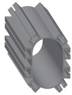
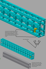
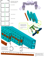
new tractor idea possibly....

   / new tractor idea possibly....
  • Thread Starter
#301  
*hhmmsss*

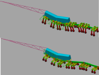
put some spacers (edited the rotatory union) to add another 30 inches. to raise sprayer up off the ground. so tops of crops would not get mowed down by the frame.

not sure if i like this idea. i suppose it could be possible. and just remove the spacers when ya change the sprayer out. but not sure if that would be feasible.

going to have to re-think the rotatory union and how i deal with the passage ways and physically mounting the rotatory union, to hold everything together.

rotatory union = it allows wires, hyd oil, compressed air, coolant, etc... to go through a joint, that can spin / rotate multi times in either direction.

then again who says i need flat solid bars, between the rotoary vane actuators, that move the wheel up and down. but rather go for 1/4 of a circle shape linkage bar. that might be the ticket there. sprayer rig does not have to deal with implements being lowered right next to tires. so i got some extra breathing room. ya... it may not give 30 inches to already approx 24 to 36 inches below the frame. but... would that be enough...

boggen elec sstt25.png
 
   / new tractor idea possibly....
  • Thread Starter
#302  
need to decided what to do, for connecting each section (section = 15 foot or 20 foot long)

i need the following...
--- hydraulic cylinder to push the 2 sections apart and then pull them back together. say 24 inches.
---say 30 degrees of rotation on 2 different axis. so each section can follow hills and slopes better.
EDIT: 1 axis rotation = twisting wrist left and right, 1 axis of rotation = bending wrist up and down.
EDIT: flatten your hand out, and twist / rotate hand as if it was the SSTT sections driving over hills, that were constantly changing direction of slopes and at different angles.
EDIT: take step further. think how pathing of say a planters connected one section, vs another section and gap between those planters as things rotate and bend.

of the 3 notations. i need to physically lock the hydraulic cylinder, and the 2 30 degrees axis rotations. so everything lines up nice and straight. when some sort of hydraulic cylinder, or rotatory vane actuator, or other moves. so when all said and done all sections line up nice and level / straight with each other. for transportation mode.

locking, could be done via wet disc brakes, or drum brakes, or even some sort of mechanical linkage that clicks into place.

each of the TWO 30 degrees of rotation. needs to be "powered" with a hydraulic cylinder, or electrical actuator, or motor, or rotatory vane actuator, or other like ways.

==============
may seem odd, but i can either place complexity in between each section. or i could require every single implement out there to try and deal with the complexity on its own. instead of multiple repeating across wide variety of implements. i rather just get it done and over width at the SSTT.

most drivers / farmers, most likely will never use manual control, of these connection points, but rather just let things happen automatically.

boggen elec sstt26.png
 
   / new tractor idea possibly....
  • Thread Starter
#303  
rear end of a pickup truck.... engine to transmission, to drive shaft, to rear pumpkin / final drive, to axles, to brakes, to wheels.

removing extra junk...
drive shaft -> rear pumpkin / final drive -> brakes.

instead of engine turning things, wheels in idea turn things....

but how do i attach a hydraulic cylinder.... to obtain that linear motion. of pushing / pulling sections apart / together.

boggen elec sstt27.png
 
   / new tractor idea possibly....
  • Thread Starter
#304  
what makes sense?

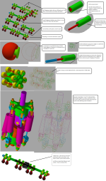
i think i am going to go with the very bottom set of diagrams, in attached picture.
ends up giving 3 axis of rotation and 1 linear movement.

--thinking the "central" hyd cylinder. allow it to slide into the main frame itself. and drill a couple holes in top of frame. to drop some quick discount connects onto the central hyd cylinder. and toss a 2 to 4 pins around the cylinder and frame to lock it in place. then the extra (side wing) cylinders, give ability to take on /off, perhaps for some implement or contraption that needs that few extra feet.
OR
--skip all 3 hyd cylinders all together. and use some short brackets and some pins. to save on cash. and lock everything together. ((would only have 2 axis of rotation.
OR
--skip the RVA (rotatory vane actuators), and the 3 hyd cylinders. and just go with brackets. to have virtually a 60 foot solid main frame that does not flex.

cheaper one direction (solid 60 footer frame), to more expensive / complex, to have each section almost operate like a 4 wheeled wagon. and a tongue connecting between.

more expensive / complex setup. could still be treated as a single 60 footer main frame. by locking disc brakes up on the RVA's, and some sort of pin maybe on the hyd cylinders.

==========
hhmmsss locking out hyd cylinders...might add a 2 foot extension on central hyd cylinder. so i can poke some holes through extension, granted it would set central hyd cylinder further back into main frame... but...

===========
alright, think i am done for now, on niddy gritty details. and move on to engine, radiator, hyd oil cooler, hyd pump, generater head. need to get some idea how much actual space they will take up. and how they will fit. before actually getting implements folding up, or turning SSTT into a sprayer or wagon or like.

boggen elec sstt28.png
 
   / new tractor idea possibly....
  • Thread Starter
#305  
engine types... *yikes*

the SSTT. i am limited by 8 foot by 60 foot, by 14 foot height.

wanting to place, fuel tank, cooling (radiator, hyd oil cooling), batteries, generator head / altenator, engine, hyd pump, along the 60 foot . and placed right up against the edge.

so i have say 7 foot open trailer, and then 1 foot taken up by all of above. and above can take up say 6 feet height as well. though i would like to keep height down to a min if possible.

to above.
8 foot dimension of SSTT, is most critcle. less i take up the better of the 8 foot width.
and then the height is next.
and then 60 foot i could less about.

=============
it would be nice to try and balance weight out across the 60 foot.

say fuel tank near end, and at a corner, so tank can be filled form 2 different sides.

engine, hyd pump, generator, most likely going to need to be one almost solid mass of metal. and be placed in a middle section of the 3 to 4 sections of the SSTT.

batteries, fuse box, relay box, most likely want on opposite end of fuel tank and located at corner, so easy access from 2 different sides possibly

radiator/s and hyd oil coolers... and just plan how do i focus things. so air is blown through the radiators/coolers. and across the engine, i am tempted to place radiators / hyd oil coolers either, on same section that has, (batteries, fuse box, relay box, and like), or on there own separate section. to help balance weight. and easy of cleaning the coils out.

==============
still debating if i want to go with a "fixed" frame setup for everything. vs being able to "angle them out" to use as counter weight.

thats right, counter weight, boxer arms. as well.

but getting back to angling the stuff out to the one 60 foot side to use as counter weight. i would need the 2 axis of rotation between sections so that i could, "twist" different sections almost, to allow for more even "weight" across the entire 60 foot. and the tires attached to each section.

granted all wheels lower and raise up and down. and i could control ground pressure per tire. that way, but if one section weighs heavier than another section, i would need the connections between sections powered. so all sections, the frames act like a single solid frame, that can be twisted / bent between sections. . but what good does that do to me on "fulcrums / levelers (tetter totter)" and being able to transfer that counter weight across and between sections.... ya that will still work, in transferring weight.

==========
if i do setup fuel tank, engine, hyd coolers, radiators, batteries, fuse box, etc... up on some linkages, so they can be folded out / angled out, to act as counter balance weight. do i want to turn the linkages into hyd cylinders, or perhaps telescopic hyd cylinders.

*rubs chin* i suppose it could be angled out, during transport mode, and allow for say an extra foot or 2. on top of the SSTT main frame. to fold up an implement, that is having a hard time folding up within say 6 feet. or simply use the folding/angling of the components, to act both as counter balance while in field, and have a bottom plow, chisel, planter, discs, etc... down, but also as counter balance during folding of implement up on top of the SSTT.

hhhmmsss....

i suppose if the engine and fuel tank and rest of components folded/angled out. and were on say telescopic hyd cylinders. i could make nearly entire 8 foot size restraint, and be able to fully use that 8 foot platform. and then lift everything straight up into the air. for stacking round hay bails between main frame of the SSTT, and the engine / fuel tank and resot of the components.

============
i don't know about this folding / angling... how in the world would i physically make those connections, for linkages, hyd cylinders, RVA (rotatory vane actuators).

reducing things, how and were would i make connections, if i skipped the folding out / angling all together...

===========
===========
===========
guess i am going to get wheels attached to the new frame setup for the sections. and place tires and there linkages on. and start marking out "row spacing" for different width rows. and see if i can find areas that i can use for support frame work, for engine, fuel tank, and all the other components.
 
   / new tractor idea possibly....
  • Thread Starter
#306  
have been having problems, that slowly getting worse, with random computer freezes (keyboard, mouse, screen) and requires reset of computer, bios of motherboard resetting on its own. cpu over heating. data corruption due to freezes. slowly been trying to diagnose issues, removing software, reinstalling drivers, running memory tester, cpu tests, last night / today, did format reinstall finally, and still issues, called asus up, and they RMA'ed the motherboard. hopefully all will be settled in first few days of next week. until then, hopefully i can keep on going, without a complete hardware failure.

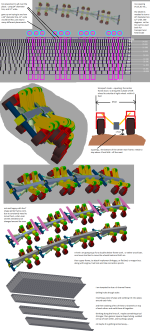
((see attached picture first))

wheel spacing, and trying to meet a wide range of different row spacing. i got defeated. just way to many different row spacings and not enough room.

up to this point been trying to stay with a 12" x 16" main square tube frame that is approx 13 feet long. once i started trying to add different "frame works" for say a hay wagon frame work before the floor is put down, to sprayer rig setup, to simply adjusting linkages to fold/unfold implements. my thoughts have changed....

to some sort of "track setup" kinda like track lighting, were you can slide a light around on the track, but there really is no wheels / rollers / other. just metal to metal sliding. and some sort of bolt / screw to possibly fasten light in place to keep it from moving. though i think i am going to go for some sort of "double track" one lower track, to adjust wheel spacing. then an upper track. to adjust linkages that fold/unfold implements. or were you would attach frame work to turn SSTT into a wagon or like, to linkages to engine / fuel tank / etc...

problem is, not sure what type of track to use or how to even set it up.

========

i suppose for wheels and the linkages for them, i would want to be able to just undo a hand full of bolts, wires, hyd hoses, air hose, and pull entire wheel off. without having to remove a bunch of other wheels from the given track.

i really do not need a big complex track setup. just a "lip" of some sort that would allow things to slide, but not allow things to come crashing down to the ground. figure sliding will require some sort of farm jack, or chain / pulley / snatch block. or someone using a fork lift, with what ever chained to forks, or lifted up into place with a fork lift (forks on FEL as well). perhaps forks used to slide stuff across the tracks as well for adjustment.

i figure some sort of "clamp" pipe clamp, muffler clamp, or there about, or perhaps some actual holes were pins or bolts could be used.

maybe a "wedge" setup instead of clamps and/or bolts. folks been using wedges for years in wood working. hmmmsss bending, wiggling, pounding wedges out, deformed wedges...

i need space for the central hyd cylinder, (that is used for between sections) that takes up 3 to 6 feet of the approx 13 feet length of the main frame / track. so what ever ends up getting used. is going to need to compensate for that, to allow attachments around the hyd cylinder.

i will also need a way to route, wires, hyd hoses, air hoses, etc... through and around the main frame / track. and allow for connections into them wires, hyd hoses, air hoses, etc... i guess what makes sense is making this stuff, run on the outside, maybe in a U channel, or perhaps some way to zip tie everything up. errr ok zip tie bad idea, due to heat. wires on one side, fluids / air that could become extremely hot on other side of frame perhaps.

i wonder... if i went with a 8" outer diameter of the "central hyd cylinder" that is used for between sections. and went with say a 8" inner diameter 8.125" outer diameter pipe. (to allow hyd cylinder to slip in) and then for hyd hoses (say max 3000PSI), used metal pipe, and physically welded the pipe to the outside of the 8"/8.125" pipe. then did same thing for coolant hoses. instead of using rubber hoses, use a metal pipe. and welded the smaller pipes to the 8" x 8.125" pipe. and repeated for air hoses, instead of rubber, go with metal pipes, and weld. and then for Tee connections. cut into the pipe of wanted fluid / air. and then weld on some sort of Tee shaped fitting. maybe using a dremal, or grinder for the cut. "maybe a drill"

bah... as soon as i put a tee fitting / nipple that stuck out. i would be in trouble for trying to slide a wheel or something else over the area, let alone trying to place something over the area.

*rubs chin*, do i just go with "pipe hangers" that fit on the 2 sets of tracks. and hold the wires, hoses, etc... away and off the tracks... well hhmmsss... ya first hose / wire that sags to much, and "snap" there goes entire machine setting dead.

am i going to need a triple decker setup. lower track, for wheels and there linkages, middle layer wires, hyd hoses, air hoses, coolant, etc... and then top track for implement linkages, wagon connection, engine linkages. its starting to turn into a "spine" of some animal... *gulps*

alright lets go off that statement of an animal.... treat wheels like, having 2 legs. other words, wheels would be in sets. wheel directly across from given wheel ... naa... well... hmmmsss.. i need to keep with wheels on each side do not have to line up with another wheel on the other side, along with keeping possibilty of allowing wheels to be lined up (directly across from each other) possible.

would an upper case I, or rather H beam for upper and lower track work? or would i be better off with... shape something like.....

|-O

one side of H beam more of a circle, or perhaps half circle...

|-(

...................
lower frame |-( wires )-| top side of top track.

hhmmmsss i guess i could still do wedges or rather i should say spacers to deal with odd shape H beam. and pipe clamp / muffler clamp. things. but how do i route holes and ends of clamps. around the area for wires and hoses.

hhmmsss.... 2 H beams, welded together with some say 2.5" long, 1" wide, 1/4" thick strips of metal. that overlap 0.5" onto each side of each H beam.

|-|=|-|

well....

|-|-|=|-|-|

hhmmsss

-|-|=|-|-

back to...

|-|=|-|

*decides to turn monitor 90 degrees*

-|=|-

(|=|)

)|=|(

)-|-(

><>< might be something.

>|<

<> simple square tube, turned 45 degrees. maybe..

++
++ 4 pluses turned into a single square pipe in center, and 8 legs stick out.

++
++ above and turned 45 degrees maybe?

<| triangle? point is down, flat on top.

<|
<| triangles point down, flat on top?

>+<

never thought i would end up doing character art, to figure out how to build something.

time to post / save. before i loose info.

==========
boggen elec sstt29.png
 
   / new tractor idea possibly....
  • Thread Starter
#307  
trying to re-invent the wheel again *rolls eyes*

not sure what "correct term" to call it.

i have seen "metal" shaped into a C shape. (rather a more Square shaped C), and then use of a square shape washer, that also doubles as a nut, that slides into the C metal frame. and a spring is used to hold the combo nut/washer to the "front / open side" of the C. the spring is used primarily to make it easier to keep washer positioned during mounting something to the C shape frame. the washer/nut may have a couple little nipples to help hold the spring in place. as you slide the washer/nut and spring down the frame to what ever position is wanted.

while C shape may not be as robust as a square tubing of metal. when ya sandwich the (open side of the C) between washer, and what ever is being mounted. it basically turns the C shape frame into square tubing, right at those mounting points. and you are no longer trying to fasten to some lip.

due to overall length of say 13' if going for 4 sections per 60 foot. or 18.5' if going with 3 sections per 60 foot, going to assume the open face side of the C frame, is going to need a little bit of extra support. i have not been able to think of a easy way to create multi C frames out of a single piece of metal. so most likely the C frames will need to be mounted, to each other or central frame. thinking some of the bolts that are used to fasten C frame to the more central frame. could be double duty. first fasten C frame to central frame. and then extend threads out of the open side of the C. so another washer/nut could be put on. to help sturdy up the C face. if ya need to slide a wheel linkage, or something, and this lip re-enforcement, is in way. just swap the re-forcement out for shorter bolt. and put the longer bolt in some place else.

i would imagine, at manufacture time, or at dealership before delivering to customer. a few extra square shape washer / nut combo's could be slide into the C frames. and a short cheap bolt put in. to just hold everything, and keep the stuff from rattling out. so if farmer ever needed some extra connection points, they would be there, and could easily slide across the C frame, without having to tear multi wheel linkages off, or implement linkages off.

awe heck, above sounds all good, but reality, most likely some folks, will have to pull off a good amount of things off the C frames, just to slide that one extra washer/nut combo into the C frame.....

i would be afraid if making a "slot" or 2 over the entire length of 13' or 18.5 feet. to try and allow insertion of washer/nut combo. without having to pull everything off. would result in C frame wanting to bend and twist and get all deranged. even if i went with say a more rectangular shape washer. that had 2 or more holes in it, that were threaded, to create multiple nuts like doing. even if i used re-enforcement areas over the slots. i don't know. just seems like a bunch of extra, that would require a much beefer C frame setup. not sure if it would be worth while long haul. i guess if C frame being fasten to more of a central frame. a person could always replace a C frame, if they completely boggered it up. though was trying to avoid actual thought of needing to replace C frames, with exception of special cases of rare accidents that would most likely happen.

===========
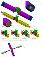
not happy yet. C shape channels but not how to there put together.
boggen elec sstt30.png
 
   / new tractor idea possibly....
  • Thread Starter
#308  
feel like i building some air plane not sure if that is good or bad.

not real sure if it will work. i want to keep the C channels, to keep everything adjustable. ya i am sure i could go through a bunch of numbers to fine X amount of holes to drill to meet majort of row widths out there. but going to take lazy route.

tempted to go with just square tubing for everything, or pipe and skip C channels all together. but then every thing that attached directly to main frame. would need to have a larger size "plate" with some extra holes. to get around the "ribs".

the 4 central C channels, not sure how to keep them from easily bending outwards. besides putting some sort of clamp or band or something across the 2 sides, i really do not want to weld something place. but not sure how else to go about it. *looks confused*

boggen elec sstt31.png
 
   / new tractor idea possibly....
  • Thread Starter
#309  
dad clue'ed me in on....
01052011_Unistrut_US

for adjustable doings for tracks... but i have not came upon anything beefer, would most likely be needed.

been hung up on how to run, pipes / wires through main frame.

tempted to go with Square tubing vs regular circular shape pipe. even if it means make the outside of a pipe square in shape, and the inside circular. thoughts are square / flat surface, be easier to drill / torch a hole in. and the weld a threaded end of a pipe to. more so when ya having to squeeze through a frame that is rather tight fit to begin with. pipes even on the best of setups to drill a hole through them can be a tad of a pain, example setting a pipe in a vise / clamp on a drill press. get the initial drill bit slightly off a pipe. and ya end up running drill bit down the side of the pipe vs being able to get a good start.

i thought about just using threaded pipe. even with one end threaded clock wise, and other end counter clock wise. so pipe could be undone and sections removed. but it is kinda like REALLY! how in the world do you even get a pipe wrench, let alone just simple channels of various shapes in, and try and tighten / loose pipes and fittings.

i am not real interested in running nothing but rubber hoses. it can be done, and most likely add to highest degree of user friendliness. but the cost of rubber hose, and then so many "cut points" that could happen, and cut or damage the hose is up. example vibration alone, and a hose resting on a sharp piece of metal edge. i could imagine a few instances, were it looks like someone gutting an animal, and in this case, all the rubber hoses for (hyd oil, coolant, air hoses, electrical) would all end up hanging out the bottom. in one cumbersome knotted mess of things. resulting in high amount of frustration, to sort things out and clean up mess, when ever some sort of wheel adjustment was needed, or implement attached. also issue of some rubber hose catching / snagging, something it is not suppose to, and not just tearing up just a single hose, but tearing up a bunch of hoses and connections.

if i can keep the main pipe/s metal. and most likely weld these pipes into place within the main frame. i would like to think i would be able to better control "messes" and "knots" of rubber hoses. and if something did snag, it would only be that given rubber hose. the issue is how to mount the metal pipes.... needing to come off these main metal pipes to both sides. (each side = tires), one side = implement connections, other side = engine connections (hyd pumps, coolant pumps, generator head), along with trailer hookups. all these connections, and just not sure how to handle them.

i thought about trying to run metal pipe. right in line with the C shape tracks *unistrut* setup. but issue of connection points being right in way, and not allowing linkages for wheels to other to slide by. so with that connection points need to be offset deeper into the main frame. to all for the clearance that would be needed.

hmmmsss.... rectangle shape pipes might work. hhmmsss. dealing with between sections.

going need to run rubber hose between main pipes in the main frame. to wheels, to implements, and like. so..... do i just go every few inches with a T fitting, and put a end cap on. or some sort of quick connect fitting. and just deal with odd placement of hoses and there connections.

i guess it would be easier at manufacturing time. to put in the extra T fittings. and place a screw on end cap, and then as farmer needs undo a end cap and replace with some sort of quick connect or swivel connection for hoses. i guess that would work for liquids and gas. but electricity.....

===============

i suppose i could do same then for electrical connections. and using wire harness connetions. and just put "blanks" or end caps over wire harness connection points.

though do i add a pig tail (a foot or so of extra wire length, that tees off main trunk of wires) i guess that might work better. wires can be flexed and bent around things. allowing main trunk of wires more hidden and less accessible. and just rely on dangling pig tail wire harness connections. but how do i keep the extra pig tails not in use for what ever reason from, flopping around, almost need some sort of, "hole" drilled into something, were i could push a cheap plastic pipe/wire hanger into. i am not sure "zip ties" would be ideal. could work i suppose, and more likely end up getting used, vs paying a few cents more and waiting for shipment of the manufacture plastic wire hangers.

do i go with longer pig tails. so they can be wraped around main frame on purpose. and more likely come undone and get torn up. or do i go with shorter pig tails. that really can not be tied up. *just to short* or do i go with say a mount for the wire harness connector much like a plug on rear of truck, for trailers and like. hhhmmmsss, some bozo "other words me" giving a yank at some connector and pulling wires out of the rear end of connector. or damaging connections inside wire harness. if i went with a mount the mount and wire harness more likely take the force.... but the issue would be, reaching over and around tires and linkages. to get to mounted to the wire harness connections.

if i stayed with dangling pig tail wire harness connections, more likely to grab a end turn it for a better direction to put in some grease/oil to keep connections from corroding up. and simply to be able to physical grab a hold of, to see if there is any problems inside the wire harness connection.

i suppose if i went with a longer pig tail wire harness connection, and zip tied the little extra length, up to main wire harness, so if wire harness connection ever did get torn up pretty good, a simple "cut" of wires, could be done with a little extra wire there to deal with things without having to splice in longer wires.

man, it is just all those connections, and good chance not all of them would get used a couple may rarely ever get used. and rest depends on crop and if tilling, planting, harvesting.

be nice to be able to just "shove" non used connections up into some sort of "holder" *grumbles* without creating a place for mice to nest or crawl into. hhmmsss some sort of end cap / cover cap maybe. drill hole through center of it. and bolt it to the frame. it would keep end from dangling and getting caught up into stuff, and hopefully keep dust / rain / water / moisture from getting into the wire harness connection. i suppose act as a "holder" for other end of wire harness connect end cover cap. when ever some wheel or implement connection needs to use up the given wire harness connection.

===========
kinda talking my self into longer pig tail wire harness connections. for electrical connections, but is that a smart move or bad move...

i doubt these connections be changed that much, maybe 2 times maybe 3 times a year. if machine used for different crops with different row spacings. some wheels may only get move a couple inches, and may not need to redo all the hyd hoses, and electrical connections. to another set. while some wheels may...

same goes from changing SSTT (sideways snake train tractor) from tillage / planting mode, into say a sprayer or wagon setup. regular implement connects would be made at end of the linkages, and not to the main frame when swapping implement for another implement. well i say that. but some third party company may end up redesigning completely different concept. that requires physical connection directly to the main frame.
 
   / new tractor idea possibly....
  • Thread Starter
#310  
getting into a more niddy griddy detail...

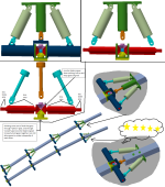
to make use of space between each side, i am down to using "rectangular shape" pipes. problem with square / rectangular shape pipes. vs circle shape pipes. is pressure bulging out square / rectangular shape sides. so.... thinking about using a bunch of L shape pieces of metal. and some flat pieces in the middle. and weld it all up. talking roughly 25 welds approx 13 feet long each.

as much as i do not like idea, of using square shape tubing, for fluid and air flow through them and the friction loss that will occur. only way i can think of, that would make "most use" of space. and still most likely meet required goals. of GPM (gallons per minute) or CFM (cubic feet per minute) the other issue, is trying to compact everything together. and balance flow throughout the piping system. and still get some sort structural support out of it all.

as much as i am for. flexing and allowing things to bend/twist within a certain amount / tolerance. i am trying to avoid, making this massive support beam / main frame. that everything connects to. but rather use everything that will connect and go through the main frame. as a way to structurally re-enforce everything.

with above said, i am still not satisfied with current chicken scratches. ya a good amount for thickness of metal, and distances between ribs/support braces, will come from structural analysis. but just not happy overall, with how hoses and wires will be dealt with. there is still a sense of major frustration. that i get that would happen when changing tires for different row widths and like.

boggen elec sstt32.png
 
 
Top