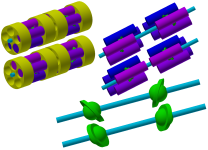
"top left change langauge", bottom right, click motoren. and get listings of animation of a bunch of different designs.
ringmotor verbrennungs-motoren pumpen multifunktionsaggregate combustion engines
listings of various types of rotary engines.
Open Directory - Science: Technology: Energy: Devices: Internal Combustion Engines: Rotary
(yikes!) long list
List of aircraft engines - Wikipedia, the free encyclopedia
getting there but not yet...
Pistonless rotary engine - Wikipedia, the free encyclopedia
a bunch of engine types (history)
Rotary Steam Engines.
more for myself, to refresh my memory of how fluid dynamics occur. and the idea of how a shaft like turbine engine might work.
The Altmann Combustion Force Turbine (CFT)
wave disc engine? hope got correct term.
MSU researchers create a new engine prototype (w/ video)
Shock wave puts hybrid engines in a spin - tech - 15 March 2011 - New Scientist
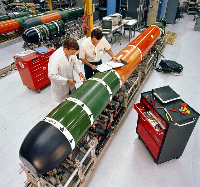
torpedo engine
Russian Military Forces | Aviation | Navy | Infantry firearms | Communications | Ground systems | Weapon photogallery
something to judge things by.
Ward's 10 Best Engines - Wikipedia, the free encyclopedia
peswiki.com has caught me off guard over last few months, and end up seeing a varying different contraptions.
Directory:Engines - PESWiki
a list of manufactures of truck engines but not sure what is required to get listed.
Deprecated Browser Error
==============
fluid dynamics. just seems like aaaa what is that? as i look at some engine types, and i scratch my head. in trying to make the most use, of the explosion of air/fuel mixture. and ensuring the entire air/fuel mixture is used up before leaving the exhaust pipe. along with transferring that explosive energy to wanted component. i see more 2D vs 3D visualizations. and just like aaaaa.... i see more flat surface to flat surface. vs a curved surfaces that might better focus explosion of air/fuel as it expands. kinda like treating the explosion like a solid rod just extending through a combustion chamber or in a piston/cylinder. vs actually identifying eddy currents within the combustion chamber. and focusing things as i look at various engine types.
i see a good amount of movement but there is still trading one vibration, for another vibration. but its not not as noticeable because you can not feel it by just touching the engine.
i gotta question some designs were not the full amount of exhaust can be expelled. (larger area of the combustion chamber or in a piston cylinder, is left with exhaust before next stage)
still soaking it all in.
==================
==================
back and forth, back and forth....
below video...
Gas Turbine Animation - YouTube
and remembering about, how air to fluid pumps and fans work when in series vs parallel. and when pumps/fans are placed in series, pressure is raised, and flow rate stays the same. when pumps/fans are placed in parallel, flow rate raises, but pressure stays the same.
so no i am getting more head strong towards turbine engine.
i would like to stay with min of 3 sections. possibly 4 sections.
1 section, engine, generator, hyd pump, air pump for tires,
1 section, for fuel
1 other section, never really came about anything.
thinking that third section, becoming an "air filter" yep 13 feet long air filter. minus a couple feet, for say batteries, fuse box, and like. small stuff. perhaps combining radiators / hyd oil coolers. into the air filter setup. maybe "heating up" air going into turbine. there would need to be most likely brushes and air jets to do a generic automatic cleaning of air filters. (not perfect cleaning, but enough to keep things going)
as much as i would prefer lower RPM's to deal with bearing life. i need to wrap my mind around, those high RPM's might be a good thing. higher RPM's at generator might be good thing. it is not like i am using a transmission, to put power through drive shafts and gears directly to the wheels. but rather, using electricity most likely, so i really do not need to worry about gear ratio's. a higher RPM would most likely give a higher frequency, of electricity. might be nice in that respect. if i went with D/C vs A/C. D/C would more likely have a much flatter line with less min dips within the line, when having higher RPM's.
hyd pump. i could use smaller size diameter pistons. to get a desired GPM (gallons per minute). due to higher RPM's. most likely faster reaction times. between pump turning on/off or when something that requires hyd fluid to do something.
problem is, the cost of a turbine engine. and parts. more so bearings.
other issue, is such a long main shaft/shafts. if the main frame section, gets nailed. or vibrations come in through the wheels. i would be kissing the engine good bye, as it shatters into pieces. i suppose it would depend on properties of material the main shaft/s is made from. that would allow some deflection / bending slight twisting. without any major ill effects.
*rubs chin*
between, hydraulic pump, generator head, air pump for tires... which ever one produces least amount of heat, and less effected by heat would be 1st. going to guess generator head would be first, due to all the wires and insulation on the wires. then air pump for tires, then hydrualic pump. then compressor/fan blades for engine, then combustion chamber, and then turbine/fan blades.
so how do i deal with wires coming off the generator, and placement of fuse box/s. i say fuse boxes, but most likely have computer chip, fuses, relays, and were main wire harnesses would connect per each section.
================
alright, need to collect my thoughts some. as i have chicken scratching in autodesk.
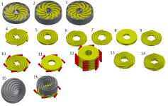
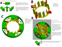
DESCRIPTION OF ATTACH DIAGRAMS!
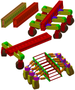
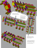
continuing off of last set of diagrams in last post of mine.....
1. using circles and cutting them up to make "vanes" air enters through the center, the blades/vanes turn. an explosion happens, then blades turn more. and the air coming from center helps push exhaust out, into an outer ring.
2. same as 1, but trying to see how doubling them up would look
3. same as 1, but looking to see if i could change direction. of one of the set of vanes/blades. to act as a better "compressor" to compress air and or air/fuel mixture, before the explosion happens.
4. went from circles to "spirals" to make better use of space.
5. remove extra garbage on the inside and outside of creating the spirals
6. turn the spirals into actual pipes, that are bent into sprials.
7, 8,9 7 and 9 are 2 halves that would have to make up #8. no other way to get around it, for actually machining the pieces out.
10. trying to show "flames" or rather explosions coming out the ends of the 6 spirals.
11. hiding things away, and showing what the blade/vanes would more likely look like with flames / explosions coming out the ends.
12. wanted to see how things would stack up. i really do not like the "straight" notations. and most likely would want to "spiral" the flames/explosions around the entire center drive shaft. to possibly pickup some better explosions efficiency.
13, 14. just trying to see if i could stack more vanes/blades in a more compact form, and if it would pay off or not.
15. thinking about changing spirals from "flat" spiral. to more of a "coil" like a spring. so air coming into the pipes/vanes/blades. it is not having to take a sharp sudden 90 degree change of direction. and in that loose my velocity (think miles per hour) of how fast the air is moving along with "pressure" loss.
16. trying to see if a squirrel cage like fan, might produce a high enough pressure, for everything. and frankly i doubt it is possible. at least in the space i have available. granted i will most likely proven wrong some were down the line. but the issue with squirrel cage fan is, it causes air to change sudden directions multi. times. and it would require extra space, that simply is not there, at least at first glance. and at this moment in time not worth while for me to look into.
==============
a regular turbine engine for say a air plane/jet, helicopter, boat/ship. has something going for vs the squirrel cage fan above. and that is how the "compressor" or i should say "box fans" you might have in your house during summer to cool off.
if you took one box fan in your home, and put say a large 50 gallon trash bag around its sides, and used say ducttape to hole bag in place. so fan would blow air into the trash bag. the bag would inflat. but most likely not stretch or pop.
now if you took TWO box fans same size, and taped both of them together. (front of one fan, to back of other fan, and then into bag). you may see the trash begin to stretch possibly even start to tear a hole.
now if you took say FOUR box fans, (front of 1st fan, to back of 2nd fan, then front of 2nd fan to back of 3rd fan, then front of 3rd to back of 4th fan, the trash bag. as soon as you turn all 4 fans on at the same time. the trash bag would most likely expand and POP! within a fairly short time.
your not creating "extra air flow" you are creating extra pressure by doing this. just like if you blow up a balloon, as balloon gets bigger and bigger it gets harder to blow up the balloon, eventually balloon gets so big it pops.
the extra pressure, when looking at a piston/cylinder. when the piston goes down within the cylinder, it draws in air and/or air/fuel (pending if diesel or gas engine). when the piston comes back up. valves close, and the air and/or air/fuel mixture gets compressed. and some place right before or during or after, as the piston comes all the way up, and right before piston goes down, the air/fuel mixture explodes.
for a turbine engine. there really is no "piston" air needs to be compressed, non stop. there can not be really any sort of pause between non compressed air and compressed air.
alright getting back on the "box fan" example. normally on most house hold box fans. you have low, medium, and high settings. low = lower RPMs, and high = higher RPMs. more RPM's = higher air to flow and a stronger wind that is felt, when dealing with turbine engine, and trying to compress the air. higher RPM's cause a higher compression of the air. (more RPM's = more pressure that gets created and compressing of air happens at a faster rate).
=========
my issue is, how do i control the compression independently of the turbine. (explosions / constant flame). what i am trying to get at. would it be worth while. to say put a transmission between, the compressor (bunch of box fans), and turbine (explosions/constant flame) so that, i can achieve different compression ratios. and also at same time control different amounts of fuel that get pumped into the engine. so that i might be able to achieve a "wider" range of efficiency, both say idle, to 100HP range, 200HP range, 300HP range, 400HP range 600 HP range. ((other words an all in one engine))
or do look at reducing transmission losses. and going with a transmission setup, that might allow better efficiency. say (gear transmission vs HST transmission). and require "engine swaps" to gain those extra few percents of efficiency. when X amount of HP is needed. to gain better fuel use.
things get a tad more complicated....
a turbine engine, needs to stay running at higher RPM's when at idle. and this of course uses more fuel. to obtain that higher RPM. if have fields that are relatively all flat, narrowing down a HP range say between 300 to 350HP might be possible. but if your fields are hilly, and ya going up and down hills. that range maybe more like 250 to 400HP. (250 going down, 400 going up hills). a engine that might be less efficient overall (using HST transmission for compress). might prove more fuel efficient, overall, when dealing with large swings of HP requirements. and when considering multi type of implements. that require less or more HP to pull them through the fields.....
BUT... would it be better setup, for a engine matched to implement type of thing, and going with a gear transmission.
===============
i need to get into a different mind frame. of current age tractors and there implements. right now, it is more of sizing tractor and implement together. but with the SSTT. the frame work, wheels, etc... will be set at a specific overall "width" example 60 foot wide. and that is not going change. SSTT to SSTT. but implements connected would. so i guess. i should look more at easier "engine swapping". and focus more on trying to achieve higher efficiency in selected HP ranges. for the different engines. and for now shooting for the "largest" of the HP engine. to make sure there is room / space for it. and then smaller engines. would be easier to drop in and go.
yikes, talk about a ramble to figure out about going with HST or gear transmission, for dealing with the compressor (box fans). and i am still not really sure what may be best, i guess engines will become like implements for current age tractors. were different manufactures, will offer different engines for the SSTT. vs offering a whole new set of wheels or tracks, and main frame, and cab. they would just be offering "engines". in attempt to gain market share. and perhaps focus on smaller markets, were a different type of engine, or HP range, or like might work better than some other engine. to a point of offering diesel, to gas, to jet engine fuel, to LP / propane gas engines, to pure electrical engine, and set of batteries, other. pending on location in world and what might be cheaper for fuel. or what ever the new "technology is"
===============
alright... turbine engines...
i have a dead space, between the sections that make up the SSTT. that hole "pivoting and rotating" is wasted space. i can not hook up any wheels, or linkages that fold/unfold implements, i can not put any sort of support frame work for a wagon in those areas. thinking about running the "exhaust" pipe in between 2 sections.
the issue is, how do i deal with the heat. and EPA and like regulations.
right now i am looking at using the air, going into the compressor for the turbine engine, as a way to cool down, generator head, hyd pump, air pump for tires. but at the same time. is there a way to recover the heat, that would go out the rear of the turbine....
i am extremely limited on space. and will have wires, to oils, to fuel, running right across the main frame, that the turbine engine will set in. talking 1/2" maybe even directly connected to exhaust port frame work of the turbine engine. i am a little skiddish, of trying to run exhaust that is HOT!, down any sort of length of the SSTT. and at same time, if i raise the air temp going into the turbine. i would be heating up generator head, hyd pump, air pump for tires.
i really can not focus exhaust straight down, (would be dragged through mud and water). i really can not position exhaust to any side, due to interference with an implement, and melting any wires or hoses, so only thing i have left is up. or trying to run some sort of "flat" rectangular shape exhaust piping. across the top of the main frame.
i might be able. to pipe in "cool air" / intake air. from one end of a section down to other end of same section of the SSTT. and maybe. extend both intake (cold air), and outtake air (exhaust) into another section. were i might be able to allow some sort of heat exchange. between the 2 types. if i went this route though. i would most likely be better off. cooling generator head, hyd pump, air pump for tires. with a secondary smaller fan/s. so i am not heating them up. and at same time not having to run as much duct work for the intake air for the turbine engine. and in that possibly achieving a better efficiency from the compressor, and in that better fuel efficiency. granted there would be a slight loss of needing to run another cooling fan. but.... that extra complexity, may make servicing, generator head, hyd pump, air pump for tires. much easier.
--this might actually work out even better. the "screens/filters" for the air intake. most likely going to need brushes, and then some form of pressurized air. to do kinda of an automatic cleaning of air filters and screens to keep them, from plugging up solid. if i could maybe. valve the exhaust, just a little bit. so i could use pressure and air flow from exhaust to clean the screens and filters...
--an idea, but, not sure if it would pan out vary well. more so if different engines get used. i would most likely be better off, with a dedicated small little air pump / blower, like a leaf blower. to make sure everything can work. without need to "re-make/duplicate" everything based on different engines.
============
ok... back to the "box fan, and trash bag" example i been going with.
alright had the idea, and then just got jumbled up...
time to post before loosing everything
