new tractor idea possibly....

   / new tractor idea possibly....
  • Thread Starter
#321  
links... that helped me....
Pump - Wikipedia, the free encyclopedia
Gas compressor - Wikipedia, the free encyclopedia
Turbofan - Wikipedia, the free encyclopedia
Vacuum pump - Wikipedia, the free encyclopedia

search for "screw pump" on youtube
search for "scroll pump on google then clicking images.


alright, how do i adjust the "blades" so that i can obtain different compression ratios at different RPM's.

do i go with something like a helicopter blade setup. were you can adjust "tilt" or angle of blades. to gain either a more aggressive, straight up. or a less aggressive angle. to say hover in a single spot.

*rubs chin*, i guess it is going to come down. material used. the blades will need strength in themselves from breaking loose, and if say a small pebble / rock, gets in and nails a blade.

i guess i can go with say a bevel gear. (45 degree angle or something)

*rubs chin* starting to think fan blades might be a bad decision when trying to compress air, before fuel is injected and combustion occurs. it is more about. lower RPM's and wanting to keep Pressure up.

with piston/cylinder type of engine, it really does not matter what RPM's the engine runs at, the same compression of air/fuel mixture happens for the most part.

i think would be better off with a different air or air/fuel mixture compressor. that has a better way to build up the pressure and then be able to hold the pressure. being able to hold that pressure, would help deal with, controlled explosions. vs a continually combustion / explosion.

even if it was a continually combustion explosion. being able to supply a higher pressure across a large range of RPM's......

=================
looking at a "scroll pump" for compressing air or air/fuel mixture, and going to have to put it on the "no list" by the motion itself, i would be creating a compaction machine. even if i put multi "scroll pumps" side by side, and off set them. i would never be able to remove the vibration that would be created.

ggrrr then again. even a turbine and compressor for the turbine engine, both would create a vibration. but at what frequency and amplitude of the vibration...

looking at screw pumps. there might be something there. for compressing air or air/fuel mixture.

i came across this video...
a screw pump, engine.

it has nice postive displacement of a screw pump, and would achieve same amount of compression (within reason after wear/tear) over a large range of RPM's. meaning being able to compress air to a point were diesel could be injected and the diesel would exploded based on heat and compression.

the combustion / exhaust side of the screws. looks a tad to "restrictive" in video. and could possibly cause a good amount of efficiency problems. as some of the combustion tries to turn the screws in opposite direction as the combustion tries to works it way back into the compression area of the air or air/fuel mixture. BUT...

with wear and tear, and tolerances (spaces) between the screws get larger. the compression ratio of air or air/fuel mix would go down, and combustion would not have as much effect. but... hhmmssss... how do you compensate? i guess the compressor stage of air or air/fuel would be a longer screw with more points of screws locking. or i could say there is more "stages" that the air would have to go through. each stage would not need as a dramatic effect in how much air is compressed. but rather it is the multi stages and locking between each screw. that would overcome longer wear/tear.

and then on the combustion / exhaust side.... i would assume. wanting to keep things fairly short. part due to amount of heat created, but how fast a explosion happens. and trying to time the explosion, so the screws, fit more in tune with the explosion.

the other issue would be trying to keep things lubricated. both to reduce wear/tear, but also help in sealing some.

if i just sprayed oil right into the "compressor" (inlet side), i would end up having a extremely hot sputtering of oil coming out of the exhaust.

perhaps. i could go with turbine engine like doings. and kinda setup 2 screw pumps (compression stages). first stage. would for most part completely compress the air or air/fuel mixture. right up to the wanted pressure. but before moving on to the second screw pump. put a empty chamber. that is better designed to "retrieve a larger amount of oil" and then the compressed air, would move to 2nd stage. which was also tied directly to the combustion and exhaust screws. doing this would let me push more into the first stage of compression for lubrication, and get perhaps much better sealing to happen. but then when it comes to the 2nd stage of compression, combustion, exhaust. there would be less lubrication, and less sealing. and less hot oil to deal with as it comes out of the exhaust. granted i would loose some efficiency, due to not as good seals in the combustion / exhaust area. due to not as much oil for sealing. but..... i might be able to use a more expensive / costly metal or like. for this last stage. vs the longer first stage (compression stage).

i suppose by also spliting the 2 portions up. i could use different depth of threads on each screw. so 1st stage. has different depth vs the 2nd stage.

i suppose if i wanted to get really complicated. i could put some sort of transmission, between 1st and 2nd stage. so i could control CFM (cubic feet per minute) of air, at given pressure. this would most likely allow me to reach higher efficiency levels. based on different amounts of fuel injected, and in that keep the curves on a graph up to par clear across the wide range of RPM's and horse power, and fuel consumption.

if i placed transmission on generator, and then another transmission on hyd pump. and another transmission on air pump for tires... i could adjust things right down to the finite ability, of what ever the current age computer chips could process data.

hhhmmsss.... i really have been thinking about using the hyd oil lines, and coolant lines, that run the length of the SSTT (60 foot) on both sides of main frame. to help act as cooling. i may setup a better "heat sinks" errr i should say heat exchangers type of thing. ya that could work, and just leave the coolant pump/s and hydraulic oil pump. just constantly running. or rather running as needed. to help cool things.

=================
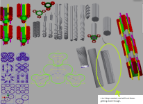
enough blah blah... the resulting chicken scratches in autodesk from above...
boggen elec sstt39.png
 
   / new tractor idea possibly....
  • Thread Starter
#322  
i do not think i could ever fit a CVT like transmission into everything, and not to thrilled about running a single long main drive shaft. so looking at going with kinda of a HST (hydrostatic transmission). were there is a single powerful pump, and then multi hyd motors. that run compressors, to generator. this should let me run "metal piping" around things for hyd oil. vs trying to deal with a drive shafts and gears and belts.

1. main engine
1.1 exhaust
1.2 screw engine (combustion)
1.3 screw pump compressor 2nd stage (for diesel or fuel that explodes under pressure/heat)

2. hydrualic pump (pump for hydrostatic transmissions *plural*)
2.1 clutch
2.2 screw pump 5,000 to 7,000 PSI max, main shaft connected to main engine via clutch

3. screw pump compressor
3.1 regulator and valve ((for 5,000 to 7,000 PSI hyd oil))
3.2 screw pump ((MOTOR)) hyd oil from 2.2 used to turn screws
3.3 screw pump compressor. 1st stage (compresses air) shaft directly connected to 3.2 shaft.

4. generator head
4.1 regulator and valve ((for 5,000 to 7,000 PSI hyd oil))
4.2 screw pump ((MOTOR)) hyd oil from 2.2 used to turn screws
4.3 generator, shaft directly connected to 4.2
((needs ability to turn opposite direction, to act like a starter motor))

5. hyd pump (for linkages or implements, augers, etc...)
5.1 regulator and valve ((for 5,000 to 7,000 PSI hyd oil))
5.2 screw pump ((MOTOR)) hyd oil from 2.2 used to turn screws
5.3 screw pump, (3000 PSI max) shaft directly connected to 5.2
(((i wonder if there might be a better regulator, to skip the 5,000 to 7,000 PSI coming from 2.2, and get 3,000 PSI.)))
((crud... may need to use this pump as some sort of charge pump possibly for 2.2, so cavitation does not happen))
5.4 using this as possibly charge pump for 2.2 and, at same time deal with "cooling" for the 5,000 to 7,000PSI hyd oil. since the 3,000PSI max lines will be running entire length of the SSTT. there would be more active cooling that could happen in these lines.
((crud, charge pump, may need to rethink that idea all together))

6.6 air pump for tires
6.1 regulator and valve ((for 5,000 to 7,000 PSI hyd oil))
6.2 screw pump ((MOTOR)) hyd oil from 2.2 used to turn screws
6.3 screw pump compressor, (150 PSI max) shaft directly connected to 6.2
((tempted, to split up 3.3 into 2 stages. this 6.3 being first stage. and 3.3 being 2nd stage. and then 1.3 being third stage))

7 water / antifreeze mix ((coolant))
7.1 motor ((pump itself really shouldn't be that big, or require to create that much pressure. so leaving it open ended for now, of electrical or hydraulic motor)
7.2 fluid pump (wet end of a pump)

=====================
as much as i been trying to "combine" things into a single doing, trying to split things up, seems to be about only way i will be able to cover all the basis.

i am not sure about all the screws, from pumps, to motors, to compressors for gas. looking at all of it as, a way to reduce vibrations. by not using pistons/cylinders. i suppose a "gear pump" might work for something, or an electrical motor for something else.


=====================
hhhmmmssss......

ok what about instead of the primary being hyd oil.... what if i went with pure electrical.....

1. main engine
1.1 exhaust
1.2 screw engine (combustion)
1.3 screw pump compressor 2nd stage (for diesel or fuel that explodes under pressure/heat)

2. large generator head
2.1 generator, shaft directly connected to 1.2
((needs ability to turn opposite direction, to act like a starter motor))

3. screw pump compressor
3.1 electrical motor
3.3 screw pump compressor. 1st stage (compresses air)

4. hyd pump (for linkages or implements, augers, etc...)
4.1 electrical motor
4.2 screw pump, (3000 PSI max)

5 air pump for tires
5.1 electrical motor
5.2 screw pump compressor, (150 PSI max) shaft directly connected to 6.2
((tempted, to split up 3.3 into 2 stages. this 6.2 being first stage. and 3.3 being 2nd stage. and then 1.3 being third stage))

6 water / antifreeze mix ((coolant))
6.1 electrical motor
6.2 fluid pump (wet end of a pump)

if i went with pure electrical.... hhmmsss the generator head. would most likely need multi coils, and in idea multi generators all combined into a single generator.

i don't know about this..... i am already looking to run a huge amount of electrical wheel motors. so generator in that respect will need to be large anyhow... but it is the air or air/fuel mixture compressors that are building up pressure to feed into 1.2 and 1.3 that has me worried. there will be a huge shift of power happening there. were a good amount power will go....

=========================
1 if hydrostatic tranmission, or 1 if generator.

when going back, trying to figure out what to use for "wheel hub motors". electrical won out over hydraulic motors, due to being able to more accurately adjust RPM's and torque going out the the tires or tracks... better accuracy for tires = better traction that could be possibly be achieved.

any sort of air bubble in hyd oil, or hoses (not pipes) for hyd oil, would cause a "shock absorption" and when i want to get that .001MPH faster, there could be a longer delay, due to air bubble being compressed, or hose expanding in diameter some. before the hyd motor of tire actually moved. that .001 MPH faster. if i go with electrical wheel hub motors, in tires, i can remove that "delay" that hyd oil would have.

if i apply same like logic, to everything above in this post... i might be able to run slightly less RPMs at 1, due to not needing to account for delays that hyd oil might cause. this is not a current age tractor. i will have hoses and wires, running 60 foot on both sides of the main frame, and there will be multi Metal pipes, but a large amount of hoses as well. that slightly less RPM's of the engine itself, would it help offset any sort of efficiency that may come from electrical, and more so weight of electrical motors.

there is a con with electrical motors. the stinking vibration, that you really you can not get away from. its all in how an electrical motor operates. and magnets and electrical magnets. granted hyd pumps and motors even screw pumps, i would imagine there is some vibration. but... hhmmmsss....

=========================
++++++++++

electrical is what it will be.... no other way around it. and should fit better for coming wave of electrical motors that will happen from auto industry for electrical vehicles. and most likely boost future SSTT versions better.

++++++++++
==========================
so what order to place everything in?.....

the exhaust is going to need to be right at end of a section. to help deal with exhaust most likely.

were does the generator get placed?!?! 2, 4, or 6

1. main engine
1.1 exhaust
1.2 screw engine (combustion)
1.3 screw pump compressor 3rd stage (for diesel or fuel that explodes under pressure/heat)

???? 2. large generator head
???? 2.1 generator, shaft directly connected to 1.2 ((needs ability to turn opposite direction, to act like a starter motor))

3. screw pump compressor
3.1 electrical motor
3.3 screw pump compressor. 2nd stage (compresses air)

???? 4 large generator head
???? 4.1 generator, shaft directly connected to 1.2 ((needs ability to turn opposite direction, to act like a starter motor))

5. screw pump compressor
5.1 electrical motor
5.3 screw pump compressor. 2nd stage (compresses air)

???? 6 large generator head
???? 6.1 generator, shaft directly connected to 1.2 ((needs ability to turn opposite direction, to act like a starter motor))

============
trying to route air metal pipes around a circle shape generator, is going to be troubling enough.
but also trying to deal with a drive shaft between 1 and generator, and going through the various compressors and motors (3 and/or 5)....

i suppose since i am going with electrical. i have a tad more flexibility. and would not have to deal with extremely high pressure hoses going between sections... so electrical motor, for hyd pump (max 3000PSI), water cooling pump, air pump for tires (might come off of 5.3) can be off set to some other section of the SSTT. allowing me to free up room to place air filtering and exhaust in the same section, as the engine itself, compressors, generator.

if i have to deal with EPA regs/laws. and needing to use exhaust heat. to pre-heat the incoming air... i am going need to route, either exhaust, or incoming air. over 1 (engine, were combustion happens). with space being what it is...and dealing with friction losses... i am most likely going to be forced. to place generator at 6. in the last order of things.... just so i have enough room to run the air intake, and exhaust....

i don't know about this... the heat from screw pump compressors, heat generated from just compressing air or air/fuel mixture, heat from generator, heat from the electrical motors. if i just placed panels around everything so intake air had to flow around it all and through it all. would i be raising air temp almost to point were it might be wanted.... and just deal with exhaust someway else. or would i be better to to put some sort of heat exchanger. right after 1 (engine were combustion happens). so intake air, and exhaust can transfer heat. bah.... what came first *grumbles*...

i guess time to rough things out, so i have an idea of actual sizes of things. so i have something to go by....

===========
before i post and head off to autodesk inventor. gearing, is going to happen at the generator and at the electrical motors. oh boy, this should be fun trying to figure out various wire sizes, coils, etc... and how to setup some sort of "smart generator" no gears here, it will all be done electrical... that's scary! gear heads turned into electricians...
 
   / new tractor idea possibly....
  • Thread Starter
#323  
looking at more screw compressors on youtube never occurred to me, to use a sliding valve. that is parallel to the screw. to adjust how much "compression" occurs. if i setup, the valves. i could for most part do direct shaft to shaft. ((screw to screw)) and would not need to ever setup an electrical motor or hyd motor. to run the screw compressors. pending on location of valves, i could adjust both CFM (volume of air per minute), and PSI that is created. and the screws would turn how ever fast as the *combustion / explosion* portion caused everything to turn. this alone would raise efficiency of everything a good deal, over various fuel types, and air/fuel ratios.

if i took things a tad further, i could do same thing for a screw pump. that would pump hyd fluid using some valves.

hhmmssss *rubs chin*

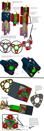
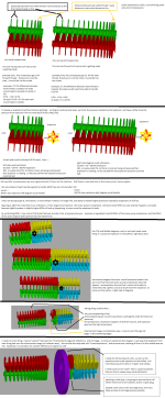
((see first attached diagram)), i am not a big fan, of 2 screw pumps or 2 screw compressors i have seen. and wondering if i should follow a 4 screw setup. were there is a central screw, and 3 orbiting screws. so the outer 3 screws for most part help keep everything lined up. ((referring to planetary gear setups)). were 3 planet gears around the sun gear. help hold everything in place. and reduces chance of gears wobbling. and binding up. as much as i am about reducing vibration, i doubt we will ever get away from it. and thinking it might be better to reduce chance of some screw wobbling along the length in the center. and causing all sorts of problems. i also have to deal with the "length" issue of the SSTT. while i might want a nice sturdy frame work that never twists, bends, warps, etc... my guess i am going to have to take a certain amount into account. and this twisting/bending/warping of the frame is going to feed right into the screws causing binding problems during operation...

hhmmsss... still need to get my mind wrapped around a screw compressor. or rather i should say, the threads.

from inlet side, the thread is thick, and distance from next thread is large. on the outlet side, thread is thin, and distance to next thread is small. i would almost need a program script. that calculates, thickness of thread and length between thread. and reduce each of the 2 numbers, down the length of the screw. making sure the screw that is parallel, does not "cross thread" , or rather i should say, stays same thickness of thread and distance between thread, but just in opposite rotation.

i guess it really does not matter screw to screw, as long as i keep counter clock wise / clock wise rotation of threads. and i could use simply "gear" approach for teeth errr threads. and just make the teeth interlock for a seal. i would just need the script to, how do i say, reduce thread pattern slightly as the thread goes down the length.

if i do the valving, i could run/use a much longer screws. that have a greater difference between intake volume, and output volume (errr compression). the entire dynamics of air to fuel ratio. would more be put on the computer chip. that controlled valving, and timing of everything. ack.... longer screws = more expansion of the metals. that could possibly cause end bearing issues.

===========
so how do i make the valves for the screw compressors.... i am going to need a good seal. so do i go with a pipe, with a plunger in it. that i can adjust with hyd fluid. or do i go with a electrical actuator type of setup. were there is a long threaded rod with nut on it. errr. that will not work. i need a "slide" like a sliding glass door, on a house. and the sliding glass door needs to partially curve around the screw. so air can by pass around the threads. when less volume of air is wanted or less compression of air is wanted. this sliding door GGRR sliding valve will need some sort of "tracks" to ride in most likely. to keep air pressure from forcing the sliding valve away from the screw.

==========
personal note for myself:
i want thinner threads, at the inlet, and thicker threads at the outlet, on screw compressor (compression stage of air) threads. so as the pressure builds up. there is extra thickness in threads to withstand the pressure that is being built up. at same time give a slightly larger "sealing face" so compress air does not leak by and go to the less compressed area behind the given thread.

for the screw compressor threads, for the (combustion / explosion) area. the same should apply as well. as initial start of explosion, and a tad moment after the start of explosion. is were i am going to guess the strongest pressure wave will happen. and will need thick threads. to withstand that initial pressure. and then as the explosion "gets bigger". threads can get smaller.

===========

before posting, my last final thoughts. after chicken scratch out stuff in autodesk inventor...

the variable setup is going to hurt in efficiency, vs being able to make and build to a specific RPM's and HP, and Torque. kinda like HST (hydrostatic transmissions) compared to manual gear transmissions. there is an efficiency loss with variable setup. but question is how much? and how much will it impact fuel usage? right now passage ways and how the slider valves are used and positioned, has me worried the most. and creating a bunch of extra friction loss if passageways are not taken into account.

boggen elec sstt40.png
 
   / new tractor idea possibly....
  • Thread Starter
#324  
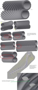
been getting my rear kicked, in trying to create "screw compressor threads".
finally came across....
Variable Pitch Helix by Equation Curve - Autodesk Discussion Groups

but still have not figured out the correct axis, and planes, and settings to get what i am wanting yet.

============
i lost, some other scribbles in a crash. in attempts to figure out if i could do the "slider valves" for the screws in a different way. and no luck there. everything i can think of would result in some triangle shape edge that is paper thin at the tip. and would be kissing that lip good bye in a heart beat. along with any sort of seal between threads.

i thought about going with holes drilled around the permeter, (in between the threads) and using some sort of secondary smaller pipe inside the screws. to align with holes. but i really would never achieve finite accuracy that way. and possibly create vacuum areas vs creating pressure. and gave that idea up.

with above said, looks like i am stuck with already drawn slider valves for the screws. though will most likely need to modify them to fit better. to better coop with compressing air, and for hyd pump as well.

============
have some extra ideas of turning screws into long planetary gear sets. but not sure if that would pan out. let alone being able to fit everything together. ((need to figure out how to make the compression screws first, to what i would like them to look like))

boggen elec sstt41.png
 
   / new tractor idea possibly....
  • Thread Starter
#325  
sorry no pictures today, just me rambling, as i try to make sense of things.

==========

*rubs chin*, i gotta question screw engine and if going in correct direction or not. searching and searching, and i have not came upon any actual physical engines, someone has made. ya super chargers and turbo charges for engines, but that is only for compressing air. as far as i can tell. and not actually creating an explosion within the threads of the screws.

i am kinda wondering, if someone some were down the line built a screw engine, for say airplanes / jets. but the "thrust" was not there. and more conventional bladed engine won out. due to able to get higher RPM's and thrust that i would assume is wanted to keep the airplane / jet up in the air. vs a low RPM that would never let the airplane/jet get off the ground. at moment conventional turbine engines for airplanes/jets i would imagine rely on some ventrui effect for extra thrust. vs a screw pump/engine really does not offer anything beyond lower RPM's possibly.

i am sure boats, to ships, to steam engines. screw blades have been used, to move the water. but there was no actual explosion / combustion of fuel within the fuel.

i wonder if there is any oil drillers. that might rely on some sort of positive displacement pump/motor. when they send these long pipes down into the ground.

====================
i am unsure about threads, and keep changing my mind back and forth.

example 1.
the screws do not actually compress. but act as positive displacement. and just pull air into the threads, and pushes the air right into a chamber. the faster the screws turn the more air compresses in the chamber. if i wanted an air compressor, for say shop tools, and had an expansion tank. were i could raise pressure up to say 200 PSI. the air compressor would turn on/off as needed to keep air pressure to wanted pressure.

example 2.
air gets sucked in. and as goes through the threads. the air gets compressed more and more. till finally reaching end of screws. (the compression happens within the screws). vs above were compression happens after the threads.


example 1, even with air leaking around the threads. the more threads i have. the greater amount of seals i would have.
example 2, every thread has to hold back X amount of pressure of air. plus any leakage.

example 1 = high RPMs to get higher pressures at a given rate
example 2 = lower RPMs, at a given constant pressure at a given rate.

if i wanted 50HP,
example 1 would have to really run the screws at a higher RPM. to get that wanted pressure.
example 2 would for most part stay same speed pending on RPM's of the combustion area.

my head starting to spin...

==================
jotting notes down before i forget them..

i was wanting to run some sort of oil within the "1st stage" of air compression. to help gain better seals. and allow a higher efficient compression of air.
this oil is going to be "dirty oil" much like "oil bathed air cleaners / filters" that have been used on various machinery. unlike a piston/cylinder engine. were it is limited area within the engine (within cylinder). and you have piston seals, and like. that help keep engine oil separated from dirty air. the 1st stage compression there really no way to "clean the air" beyond good air filters. but even then there is going to be some dust and grim that gets through.

do i want to use a common "sump" were engine oil and compression oil is all in one and the same. and flows through everything. or do i want to split the oil up. so there is a distinctive filters, and locations for different oils?

*rubs chin* i guess the hyd pump, will have hyd oil for lubrication. the little amount of grease / oil for generator head. will be limited. coolant pump (water/antifreeze), will have the water/antifreeze and what ever additives, to have its lubrication.

the 2nd stage of air compression, and combustion area. i would assume get some oil from 1st stage of compression (no direct way to remove all the oil from the compressed air).

BUT!!! compressing air. and the water that can come out of the air.... would i need to run some sort of "water absorption filter"?

figure i would just rely on some of the compressed air (directly after 1st stage compression), to push oil around. or rather i should state. pushing oil from end of 1st stage, right back to the front of 1st stage. and put some sort of valving in line. to adjust amount of oil. both GPM (gallons per minute), and amount of oil at end of the 1st stage sump area. trying to use some sort of pump. and pressure alone would run the pump in wrong direction, and/or allow a good amount of compressed air to escape right through the oil tubing and never make it through the combustion chamber.

the issue is "air locking" if i just relied on compressed air. i am guessing i am going to need to use some sort of little electrical motor. that has enough torque to counter act the compressed air pressure. and at same time help push oil from rear end to front end of the 1st stage compression area. most likely a positive displacement pump. so things can be "metered" or measured. i suppose if i did this, when engine gets shut down. this motor, could run for a few moments. to reduce built up air at end of the 1st stage compression. so if someone goes to work on something. there is less chance of compressed air suddenly turning things.

another issue at end of 1st stage compression. how do i remove extra oil from the air? been thinking of some sort of centrifuge water pump / blades / propeller / impeller or like. were air and oil hits blades. and everything is sent out and away from the center of the shaft, causing hyd oil to stay trapped to the inside casing walls. while allowing the air to flow on into the combustion area.

other issue is needing a oil tank large enough, to handle oil usage. by default this screw engine is going to use oil. or rather i state some oil will end up going right out the exhaust. and in that most likely use more oil than say a piston/cylinder engine, (i say that, because i have no idea at current moment). do i go with an oil? or do i go with some sort of other fluid, that is required for current age engines, to reduce emissions, and use that both as lubrication and sealing in the 1st stage compression. and then send that same stuff right out the exhaust?

====================
cooling... more so cooling for the "combustion" threads.... lots of explosions, lots of surface area. those threads are going to act like a reversed heat sink. and just suck up the heat.

if i go with a larger diameter shaft for the threads of combustion area. = more expansion from all the metal.
if i go with a smaller diameter shaft, = less expansion that would happen.

larger diameter might allow me to run coolant (water/antifreeze) right through the center of the shaft. the end of shaft, for combustion, one end would end up in the high pressure area (compressed air). and the other end, should be verly little explosion pressure on seal if anything at all.
well i take that back, if i go with solid single piece of metal. from first stage compression all the way through to end of combustion area. the seals to pump coolant through would have very little pressure on them. and i would only need to deal with a rotatory union / seal / coupler. that might work out nicely.

that might work out nicely, if i stay with 4 shafts (3 outer planet shafts *planetary gearing*) and then the center sun shaft. 4 lines, direct cooling from the inside. i already have "coolant lines" out the main frame of the SSTT (sideways snake train). to deal with coolant lines that run down to wheel motors or what not. i could just tap right into those lines.

question is which way do i run coolant. can i make use of the coolant fluid to act like radiant heating. and help warm up the "intake air" before it gets compressed. or do i want to mess with routing hot exhaust air through some sort of heat exchanger device to warm up intake air.

======================
getting back to start of this post. am i going in correct direction with a "rotatory screw compression engine" SSTT frame work and working out this and that is one thing, but engine as well? am i trying for to much? na... not yet, gotta figure it out, and see if it is worth while or not, or something better comes along.

=====================
alright time to see if i can figure out how to make the thread types i am wanting for the screws....

latest version i want to hit. is for a .001 thickness gear. and take say 3600 of them, and placed on a shaft. and then, slightly rotate each one. from one end offset rotation = .01 degree and as i get near the other end, each gear is offset by .4 degrees.
but i want to remove the step of making the 3600 gears .001 thick. and make a nice smooth transition. while keeping the same tooth shape. without tooth changing dimensions.

then another version with thinner teeth at the intake side, and thicker teeth at the outlet side.

the whole.... keeping same amount of teeth. and were the teeth of a gear for lack of better term. mesh together. that center line between threads as everything changes shape down length of the screw, is what has me worried. if the center line of the teeth changes of were they mesh. i could cause an imbalance were one section of threads, has a smaller and larger diameter threads, vs another part were binding would occur.

i am tempted to only go with a single main shaft. and let the planet screws (planetary gears) not have direct shafts, between each stage. if i did this. i could set the planet screws. into a different shape example cone shape shaft. and possibly go with threads, that would be much easier to physically machine. vs a variable pitch threads. well take that back. correct machine setup, would make easier work of variable pitch threads.

hhhmmss.... so many choices....

cone shape screws. may be a tad pain in the rump. to route coolant fluid through the center of the shafts. and then dealing with the "slide valves" to change CFM (cubic feet per minute) of air or combustion, along with changing pressure to make a variable HP engine.

the "slide valves" are going to automatically require a few inches on each side of 1st stage, and then 2nd stage/combustion area. more range the sliding valves are allowed to slide, the more inches on each side of each stage there will need to be. i can not shorten the sliding valves. or coil the sliding valves, without causing more air leaks around the screws.

arghs.... so tempted, to only stay with center main shaft. as one long screw / shaft / screw setup. and then not directly connect the planetary screws together. if i do not directly connect them. i could use different "gear ratios" per say, in each stage. which could give say higher compression of air at first stage, quicker compression in 2nd stage of compression, and then a different ratio for the combustion stage.

if i do not connect the planetary screws., i might be able to "offset" each stage a couple degrees. to allow room for the sliding valves. without the sliding valves bumping into each other. i was going to say cone shape screws it would not matter. but there still would most likely be an issue with cone shape screws as well and need to possibly offset each stage a couple degrees or so.

====================
diesel engine "knock"? hope i got correct term. were a diesel engine, glugs, glugs, glugs along at lower RPMs say at idle speed. and then at higher RPM's the engine knock almost completely goes away. if i am able to achieve, say 2" bore 3" inch stroke of a piston/cylinder engine one moment, and then say a 8" bore 9" stroke the next moment with the variable screw compression engine. can i keep the engine RPM's up higher, throughout the entire range of HP ranges. and reduce that "glug, glug glug" and in that possibly reduce vibration, and with that compaction possibly.

i just do not see it happening for the combustion area, as being cone shape screws. the slider valves. would bottom out into the 2nd stage compression screws. the only way i could make it possible, is either remove 2nd stage compression all together. (and really not wanting to). or split 2nd stage compression up from combustion stage. and link with a shaft, just so i would have room for slider valves. and not really liking that either. more so if i one of my goals is for diesel or like fuel. were pressure and heat is used to cause the air/fuel mixture to explode. and wanting that explosion to happen. so the explosion goes through the combustion screws. vs causing a backwards pressure wave that goes back into the 2nd stage.

hhmmsss.....

alright, straight threads (regular gear), to compression gear / threads, to straight gear (injection of fuel), to compression gear / threads (combustion threads)
well no.... hhmmss...

do i create a concentrated wave ripple maybe. na, that would just lock the screws up. and not even make them turn in favor of clock wise or counter clock wise direction.

======================
is the 2nd stage of air compression a bad idea? would i be better off letting first stage going up to a higher pressure. and opening valve, to let air rush into say a chamber. close the valve, inject fuel, as the fuel is getting carried away into the combustion screws. that way entire explosion force is directed in one direction.

would i be better off loading up the combustion chamber, with say 4 to 5 pockets of compressed air. to act as a shock absorber, and then causing the explosion that is furthest from the 1st stage of compression.

setting myself up with all the inlet/outlet valves on a cylinder/piston engine. so that i can obtain variable timing of explosions. and in that reduce overall RPMs vs a turbine engine. but feel like i am tip toeing around the subject/idea.

timed explosions.... there are going to be instances. were i revolution maybe every couple revolution. only a single explosion will happen. but during those revolutions, the screw threads are going to want to suck in air into the combustion chamber. and then act like a vacuum as the air moves through the combustion screw threads. there going to be a point were length of the combustion screw threads and just pressurized air starts to become negivite pressure and actually creates a vacuum. then say next thread coming around has an explosion happening. and i am going to assume it will take longer for that explosion to go from high pressure to a lower pressure. than just pressurized air. i doubt the sliding valve would hold up trying to do a few hundred MPH (miles per hour) switching between explosion to pressurized air. the only way i am going to get around this, is going with an explosion between every thread. so each pressure created by explosion evens out across of point between were pressure being a positive number, to point it goes to negative number. if i can even out those pressures a sliding valve would slowly move back and forth as needed.

but above brings up other problem. if i have to create an explosion between every thread (should be saying tooth of a gear) the more teeth = more explosions per 1 single revolution. if i was at 2000 RPMs and 5 teeth per screw. then if i went with piston/cylinder like inlet/outlet valves. those valves would need to move 10000 times at 2000 RPMs. OUCH! that would really kill things. a regular piston/cylinder gets away form high speed valve opening/closing due to it takes 2 revolutions for a complete cycle of (intake air, pressurizing air, exploding/combustion, exhaust). but on this screw compressor engine that is not the case.

ok what if i went with a "rotating" disc, with some holes in it. so when disc rotated X degrees the holes would line up to let air into the combustion screws. and then as disc rotated a few more degrees holes would no longer be lined up. so in that effect act like a "valve". that open/closes. that sounds better of a disc rotating around than a bunch of valves hammering the living daylights out of themselves.

but that brings up another issue. a disc is not going to handle shock wave pressure from explosions very good. so most likely will need some sort of one way check valve. perhaps..... spring->metal ball->spring. and a cylinder shape around ball. that allowed ball to close when pressure shockwave hits it from explosion. and then ball moves to other side of the cylinder to let compressed air in. the springs would be more of a way to "cushion" the metal ball. vs letting the metal ball act like a bullet and getting jammed up.

i suppose i could go with metal reeds (kinda like a mouth piece reed for a flute or like musical instrument) ya blow in, and thin metal piece bows out letting air in, and then closes back over a hole. not really liking idea of the reeds as a check valve though. have seen enough in power tools / small size air compressors. and honestly do not care much for them. though i maybe wrong.

arghs... i am still stuck with a valve or a set of valves make it check valves or like, that would be moving extremely fast opening/closing. so about only way i am going to get away from that. is to re-enforce the disc with holes in it. both sealing, tolerances, and physical structure of it.

well hhmmsss.... yep still stuck with piston/cylinder thinking. as soon as screws turn, to finish one shot of drawing air in between threads, the other set of threads coming around open up to suck more air in. to a point of a very small "pulsation" of air flowing into the combustion screws.

alright, so no valves that open/close to let air into the combustion chamber. and only using the sliding valves. to control combustion screw chamber length.

====================
alrighty then. if i stayed with last couple posts diagrams i attached to this thread. were 2nd stage compression of air happens, and directly connected is the combustion screws.

(talking diesel fuel)
i am going to guess, there will end up being a "sweet spot" some were in the 2nd stage compression. were heat/pressure gets high enough to cause diesel to begin exploding. the explosion will have compressed air behind it, (in the 2nd stage compression), and it will have compressed air in front of it (in the combustion screws. as everything turns, the 2nd stage compression, is going to try and push the explosion out of the 2nd stage compression, and into the combustion threads. the combustion threads, will have a vacuum effect to pull the explosion into it. once full explosion is in side the combustion threads. it will all be in the expansion of the explosion.

other words. the 2nd stage compression area. were the threads interlock. to point threads interlock in the combustion screws. the "volume" say cubic inches on the combustion area will need to be larger at point of explosion, than cubic inches within side the 2nd stage. the more i can move point of were explosion happens into the combustion threads. they more efficient everything would be.

so how do more insure explosion will begin to occur nearer to the combustion screws or within the combustion screws????

do i simply move injection point of fuel into the beginning of combustion screws. and make sure the air pressure will be more than high enough so even after the compressed air enters the combustion screws and begins going down in pressure, there is still enough pressure and heat to cause diesel to ignite and explode.

it would require more HP to compress air up to a higher pressure. and in that a less efficient engine overall. due to wasting power on getting a higher air pressure. but.... i would think, it would not be a huge loss. same pressure that is built up, would also help turn the combustion screws. and they only major loss will come from. is friction loss. of high pressure air moving. through everything.

though higher pressure might be a good thing, and might help "hold" the explosion pressure, from leaking back into the compression area. well... hhmmmsss. higher pressure, larger more powerful explosion, to an extent of how much fuel is injected.

=================
alright, so i am going to need to set the 2nd stage compression screws and the combustion screws. at a certain degree of rotation off from each other. so when the explosion begins, and explosion ends. the pressure of the explosion, is not against the 2 threads, are are currently sucking in compressed air. the more threads errr (teeth like a gear). the more air locks and back pressure i could have, to keep the explosion pressure leakage from getting back between 1st stage and 2nd stage of air compression.

i have been debating about it, and been trying to push the thoughts to a later time. but not happening. been thinking of using another sliding valve. to act like an injector. to locate / move were fuel is injected. possibly adding some sort of pressure sensor

also been thinking about making the sliding valves more like C shape that wrap around the smaller size screws vs using ( partial C shape slider valves. and in that. having sleeves or rather sliding valves. that could be easily replaced. to say "re new" the engine. vs relining a cylinder of a piston/cylinder engine.

================
================
================
================
recap....
--slider valves in ( and/or C shape.
--no cone shape threads, and in that cylinder shaped threads of the screws. (not sure about shaft though, guessing though cylinder shape as well)
--no inlet/outlet valves for compressed air. this includes no disc valve.
--electrical motor controlled oil pump. to move oil from one side to other side of 1st stage compression. (acts more like a regulator)
--offset degree of rotation between inlet of 2nd stage, and were "sweet spot" for fuel injection happens and in that combustion/explosion happens. (more deals with helix curve and how threads/teeth are spaced.)


depends / possibly
--thread design and tooth design per say for the screws. (un-decided)
--offset degree of rotation between 1st stage air compression and (2nd stage air compression and combustion stage)
--coolant (water/antifreeze) going through center of screws for cooling, (depends on material out there and cost of it), but most likely coolant through center of the screw shafts.
--possibly adjustable location for were fuel is injected.

unsure
--unsure how to remove more oil between 1st stage and 2nd stage air compression. to keep amount of oil used down to min amount.
--unsure if oil will be used vs some EPA or what not fluid or gas to deal with emission control.

hhmmsss... starting to get brain fried. time to post, and let everything sink in of the good's, bad's, and the ugly's.
 
   / new tractor idea possibly....
  • Thread Starter
#326  
finally, something hit me for sliding valves... and trying for less amount explosions between every teeth/thread.

timing valves of a piston/cylinders and running things off of some sort of cam. (circle shape with a triangle per say on one side of it).

a shaft that runs parallel to the screws. that has a one way clutch built in. so a electrical motor. could cause this shaft to momentary slow down, or speed up. so as an explsoin happens between one set of teeth/threads. it spins slightly to to keep explosion within the screws, while the next teeth/threads. it spins slightly more to allow just compressed air to by pass the screws so a vacuum would not occur inside the screws.

i suppose this shaft, would be a screw in itself. but the center of this screw (the shaft itself. would have another grove in it. arghs... hhmmsss.... never mind. i would end up having thread of the screws, that were never attached to a shaft.

but.... that might work for a coolant pump. inserting an "auger" for lack of better term. right into one of the larger central screws. (assumption coolant (water/antifreeze mix) sent through center of the screws for cooling) the auger would act like a "pump" be instead of moving grain up to a wagon, or bin or what not. it would just be moving water. put a some sort of clutch to stop auger or let auger to spin at same speed of the screw that the auger is in. or perhaps simply let auger free spin. i suppose some sort of gearing might be wanted, pending on GPM and pressure developed. but i would think, a person could figure out the math, to roughly size the auger. for desired GPM and pressure developed. and if more is needed. then another pump could be added. example on sections of the SSTT that does not have the engine. and electrical wheel motors or other, is just not obtaining the needed GPM of coolant and at a wanted temperature range.

i guess size for size, i would be looking at a regular wood drill bit of 1/2" to 3" in size. vs grain auger sizes of 4" to 12" in size. for the cooling pump action.

that actually might work out in good doings. and give the screws more structural support in the center, at same time, act like a heat sink. to help draw heat from the screws. more so the combustion screws. and during initial start up and everything is cold. it might help push extra heat into everything. during them first few minutes.

the one way clutch, would be there, if say the screws the material they are made out of, expands just enough, to catch the cooling auger. and not allow the cooling auger/pump to freely spin.

errr getting a few different things here...
1. were the cooling pump / auger. fits tight enough. that it does not freely spin.
2. were the cooling pump/ auger. fits loose enough, that it can freely spin.

the fluid dynamics... hhmmssss... good amount of difference. in both cases. to point not sure what may be best, or what would work out better. also issue of pure friction, of the coolant fluid and creating more heat, than what is being removed from the screws.

coolant, i really do not need a huge amount of pressure, compared to compressing air, and then the combustion stage. but rather. i need GPM (gallons per minute) the faster the coolant flows through the screws and through radiator/s. the more cooling per say could happen. and more even temperature across everything would happen.

the amount of pressure needed, would come from simply needing to over come, the friction loss, in all the hoses, pipes, radiators, etc... that shouldn't be to bad of a problem.

question would be though, would i be better off with like an auger like screw. or going with more of a box fan, style fan/pump blades. i guess auger like screw would be best choice. *forgets technically term for water pumps with a single screw* but they are out there.

hhmmsss startup of engine, i would imagine, i would want the coolant auger/pump to be able to disengage. so less start up power from starter/generator would be needed. it may only be a few PSI, of extra pressure to overcome, but that may make a difference between, in winter and more so cold mornings, and starting up, vs having to crank, and crank. if not disengage, then need to make sure "valves" and like are open during start up. so least amount of friction loss of fluid flowing through all the pipes / hoses happens.

alright need to post and really get busy on autodesk.

=================
not much progress made in autodesk inventor for the 1st stage compression area.

boggen elec sstt42.png
 
   / new tractor idea possibly....
  • Thread Starter
#327  
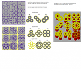
finally! figured out a way to get the compression screws the way i want them!! WOOT! YA!

from just dragging things about, it looks like everything connects, rolls, and hopefully seals decently for what i am wanting.

i do not need huge amounts of volume of air per minute at very low pressure, and i do not need extremely high pressures at very little air volume, but a mix some place in between.

boggen elec sstt44.jpg
 
   / new tractor idea possibly....
  • Thread Starter
#328  
*rubs chin* more and more i look at the screw compressor idea of an engine. the more i want to step away from it, and go with a traditional turbine engines that have actual blades, vs vanes / threads of a screw compressor. but what gets me is the RPM's and small over all diameter of the fan blades. the only way i could compensate, for lower RPM's and diameter. is to place more fan blades, to increase overall length that the blades take up. the length really not the problem, but the "intake air" and "exhaust" is the problem, and more to the point using drive shafts to connect up to a generator and hyd pump.

with a turbine engine, and all the crud that gets kicked up while in the field. not sure how i could run air intake, and hook up to air filters on another section of the SSTT. and in that routing air around the turbine engine fans and turbine itself, or routing around generator and hyd pump.

if i stay with screw compressor engine setup. i can create passage ways via using something like planetary gear setup, with sun gear, planetary gears, and ring gear. and work air passages between the planet gears ((gears in this case = screw compressor vanes)) if i tried same thing for fan blades. i would most likely get in trouble at lower RPM's and never be able to create enough pressure to ignite diesel fuel via pressure and heat.

i guess only difference going between fan blades and screw compressor (vanes), is i am creating a more physical barrier, to help compress air. and not allow the air to backfeed back out the intake in a sense. i guess that starting to make sense. screw compressor vanes vs turbine engine fan blades. would be like changing blade style for say a centrifuge pump. instead of high volume per time at low pressure, i would be changing for a medium volume per time for medium pressure.

*DUH* moment, maybe i can stay with a more traditional turbine engine setup. its just that the blades, will be sucking in the center, and blowing at the tips. arghs, still be at the mercy of lower RPM's, and not being able to create a higher compressed air pressure.

============
alright, enough doubt, staying with screw compressors.

the next issue, is i need to look at 3D model better, to see if circumference of "planetary gears" (outer compression screws), needs to be adjusted to the "arc length", between the planetary gears (outer compression screws) on the central sun gear (middle compression screw). there maybe a high "friction loss" of air traveling from one screw to next, as it gets compressed, resulting in less efficient setup.

i wonder if the vanes (teeth of a gear), can be shaped a tad better, to cause a "pressure barrier" errr i guess that is bad term, a extremely turbulent zone, right were vanes (teeth of gears), meet, that might be used as an advantage to reduce air leakage at the vanes touching from one screw to the next.

also is there a way to shape vanes so that, as the vanes go around, and almost touch the casing. can the vanes be shaped, to create an air foil or barrier of air right at the edges/tip of the vanes. so there is less leakage of air.

amount of physical full 360 rotations a single vane makes, to amount of air compression, is going to effect things i am sure. more full 360 turns = less compression per rotation. and perhaps less overall leakage between vanes. but i would imagine. there is a point of to many turns and efficiency curve of amount of air leakage, would almost flat line at some point. and same would go for min amount of turns. i guess turns is bad term, and "twists" might be better statement. of how many twists the vanes make.

the longer the overall compression screws are, the more "twists" i could make, and less compression would happen per full 360 degrees rotation. which would most likely result in a higher efficiency setup. (within reason).

were 2 compressions screw vanes mesh up (teeth of gear mesh up), one side there will be almost a "suction side (negative pressure)" and the other side will be a "positive pressure side", i will need to keep this in mind, when i place the compression screws together, of what vane overlaps the other vane on the other screw compressor. so that vanes might actually "touch" like gears, and create a better "seal" to keep air from leaking by.

never really tried to figure out were to inject "oil" into the screw compressors, along with how much. if i apply "centrifuge" style pumps. to the screw compression vanes. oil would end up at the very tip of the vanes. were the seal would end up being wanted. the only problem i have with injecting oil, is trying to twist vanes so tight, that a given amount of hyd oil could get in, and (then not be able to compress like air), and hyd oil would start to seize the screws up from rotating. and start causing a bunch of extra friction heat, as oil leaked passed the vane tips. and in that, the lubrication oil, sealing oil, cooling oil (what ever you want to call it), alone may determine how much air can be compressed down to.

alright, is going with planetary gear setup a good idea?, vs only going with 2 compression screws..... to state difference, 3 planetary compression screws and most likely larger diameter sun compression screw. vs 2 compression screws. it is not the "gear ratio" that has me concerned but rather how much air can be compressed (volume per time) and to what pressure
--planetary = higher air leakage between vanes and casing, ((more overall circumference of case)) vs 2 compression screws.
--planetary = more seals between vanes meshing together, and in that most likely more air leakage at meshing points.
--planetary = could create a physical longer path or shorter path, vs over all length of screws. other words planetary setup changes amount of twists, and amount of compression over, over all length of screws.

so what else am i missing, and need to take into account for shaping and building the compression screws????

====================
i am missing....

if i go with planetary gear like setup for the screw compressors. both planets and the sun, will need to be exactly the same except, the helix curve will need to go in opposite direction for the sun gear (compression screw), ya a little slow on that one. with that stated it gives me fewer choices to pick from...

and to limit things even further.... in order to keep rotation going in correct direction. odd amount of screws = NO NO. or less there are 2 screws that do not touch / mesh together.


=================
sent a few emails off to some companies, in attempt to see if i can find some more information of engines already out there. see what happens.
 
   / new tractor idea possibly....
  • Thread Starter
#329  
created 2 threads on 2 other forums....in attempt to find an engine that might work. to point of will work.
trying to find a engine that will fit some dimensions - Hot Rod Forum : Hotrodders Bulletin Board
trying to find an engine to fit some dimensions.

===========

below 2 pictures are from....
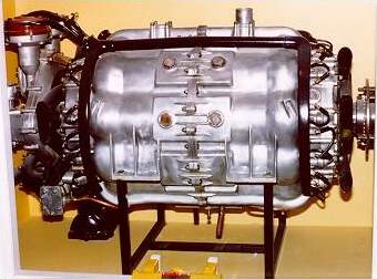
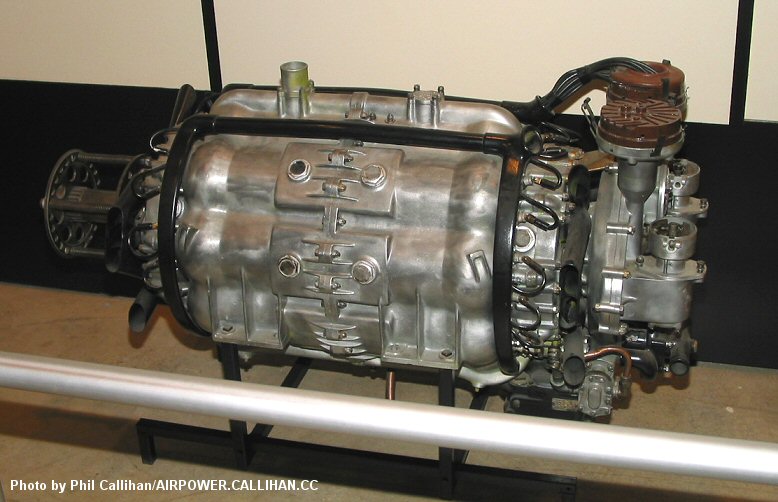
Axial Internal-Combustion Engines.
Almen%20A-4%201.jpg

04USAFM-AlmenA4Barrelengine.jpg

Output 425 HP at 2000rpm
Weight 749 lb
Diameter 20in

made back in 1921, it would be nice to find an "updated" version of this engine.

==========
dyna cam engine, much like above...
The Revolver Cam Engine (Previously known as the Dynacam engine).wmv - YouTube

but not able to find anything, that i could just go out and buy, or just call and ask for specs or like....

============
small model of above engines...
4 Cylinder Gas Powered Engine - From Gyroscope.com

==============
Turbocombustion Green-Engine Technology Assembly - YouTube
Turbocombustion Green-Engine Technology See How It Works - YouTube
might be something, but internet searching has not revealed anything... and webpage noted in video, is coming up 404 not found....

==============
mazda granted more towards air craft but....
http://www.rotaryforum.com/forum/showthread.php?t=34305

==============
need to look more at this, seems there is better categories of patents, perhaps it will let me track some engine design types down.
F01B 3 - Reciprocating-piston machines or engines with cylinder axes coaxial with, or parallel or inclined to, main shaft axis - Patents Sitemap

==========
different notes....
for the screw compressor engine... (something different)
paradoxical gear set 1,2,3 teeth - YouTube
 

Attachments

  • 04USAFM-AlmenA4Barrelengine.jpg
    04USAFM-AlmenA4Barrelengine.jpg
    84.7 KB · Views: 80
   / new tractor idea possibly....
  • Thread Starter
#330  
have been sending emails back and forth with rotaryengine.com | Rotary Engine Specialists | Mazda Performance | RX7 Specialties for last 3 to 4 days now. (most likely a nightmare customer for them, due to my own lack of knowledge, of what is needed/wanted). there website, gives impression of customized mazda engine builds. and website notation of experience of running generator setup with various engines, emails have been being returned in a timely maner. at my view, company has qualities of what I am looking for.

==========
2 barrel engine actual working demo running
Barrel Engine short - YouTube

==========
another website / video on "duke engines"
Duke Engines – 5 Cylinder 4 Stroke 3 Injector Valveless Axial Engine

i keep looking at it, and wanting the engine. vs barrel engines (seen in previous post). it is more about the "swash plate" or "wobble plate" how ever you want to define it. and staying with more of a "linkage arms" between piston, and connection point to the "swash plate" and being able to work out the load forces so more force is placed in actually turning the shaft. vs friction and rollers trying to turn a swash plate. not to sure about gas (showing spark plug) in all the videos that i remember seeing, and assuming gas vs diesel. but....i did email company a while back, and did get a quick response, noting there trying to get production stuff figured out for mass production. ((been to long to remember the email))

===========
i am still interested in the (to many terms, do not remember them all), opposed cylinder opposed piston engine setups. and for what i am looking at as far as space 20" width x 20" height. and if possible smaller measurements.... i am tempted to see what it would take to run a few barrel engines back to back. and put into the same engine block per say. to get opposed cylinder and opposed piston combo going, so i can get the "drive shaft" going in correct direction.

============
on other hand....
trying to find a engine that will fit some dimensions - Hot Rod Forum : Hotrodders Bulletin Board
trying to find an engine to fit some dimensions.

both of above threads. with mention of more of a common V shape piston/cylinder chevy small block engine... and more likely use of off the shelf parts. and redo connection points for air filter, exhaust, etc...

============
then the wankle engine, from mazda.

another wankle engine
LiquidPiston unveils 40-bhp X2 rotary engine with 75 percent thermal efficiency

============
completely different style than what i have seen to date. not so sure about getting things hooked up to the rotational part,
The Doyle Rotary Engine

============
axial vector engine, not sure exactly what is going on, not sure if dyna-cam won out. or if emireatescapital put everything under something different or what.
http://www.emiratescapital.net/pdf/AVEC.pdf
web.archive website i guess took snape shoot of website before it was given up?
Axial Vector Engine Corporation - Gallery

I have tried emails, but there all coming back as "failed delievery"

=============
barrel / swash plate engine. sent email off a little bit ago. hopefully will get a response from them.
FairDiesel Limited
FairDiesel Limited

=============
a search for "barrel engine" brings back a good list of engines and notations it looks like. have not taken time to flip through it all.
Browse Flight's archive of Historic Aviation

=============
not much info on this engine, but 150 or so HP, and fits in wanted 20x20 dimensions, i gotta tag it.
Suter Aircraft Technology AG - a smart and brilliant innovation

=============
chart of overall dimensions for cylinder/piston engines, seems folks have copied this chart around a few different places...
The Official H-Body Internet Community • View topic - Chevy Engine Dimensions

blue prints for a wide variety of cars/trucks
SMCars

possibly other forum, i might try posting to, to see what info i can get for engines.
Forum Index - ChevyTalk --The Social Network for Chevy Fans

fair discussion on various engine types.
THIS JUST IN. Hold on to your hats! But... when will it happen?

==========
speeder reducer (grear ratio thing), and hydraulic motor. maybe even a wheel hub motor possibly.
there was a better video for gear ratio. for much higher ratio that normally achieved by planetary gear setups in same amount of space.
the hydraulic motor, type thing more of a note: for myself, when i go back to detailing out wheel motors.
Interesting Speed Reducer - YouTube
hydroengine - YouTube
Hägglunds Drives Powering the revolution - YouTube

=============
needing to take a brake from engines...

the more i search through engine types, the more i am wanting to apply for a patent for the SSTT tractor. beyond relying on the statement of requiring free to use for yourself, but not make money from the idea, without written permission by me. ((see previous post some place in this thread for better notation)). basic idea towards farming would be, is just a simple "tool bar" with an engine, fuel tank, and wires and hydraulic lines, coolant lines, etc... that someone could then build off of errr i should say attach to. to do what ever. if it was marketed towards transportation, it would be a self propelled trailer in idea. or rather toolbar/frame work to attach wheels and flat bed or box like frame on it. its not really a vehicle were someone actually rides in it or on it. i suppose someone could, by attaching a cab to it some place. were said cab, was bolted/pin down. to a point were it would take considerable amount of time to remove cab. it is really not setup to be a single function unit, like a self propelled (enter something), that only does one special thing.

==============
alright time to post.
 
 
Top