new tractor idea possibly....

   / new tractor idea possibly....
  • Thread Starter
#31  
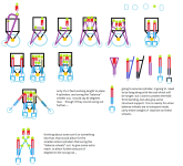
added 4 other possibility, adding in a few hinge spots i forgot to draw in. and redid labeling...

View attachment 279640

my mind says, i want to keep implement as close to the engine box / front drive wheels as possible. some of it is for folding up. part of it is to reduce stress (longer a cylinder has to reach more prone it would be to bend, just like anything else, joists, rafters, cathedral ceilings with a beam going through it from side to side....)

with above said, that would knock out row 1 completely. due to top link / top cylinder, would automatically force anywhere from 6 inches to a couple feet distance between engine box and implement when folded up. and just unfolded and ready for field use....

which leaves row 2 as possibilities.... again i am not really liking lower cylinder being placed on rear end of engine box. were the cylinder itself (not the rod) would cause a gap between engine box / front drive wheels and the implement. that would remove 2A, 2B, 2F

but for 2B and 2F what if we slightly changed were the cylinder connected to engine box for these 2.... by moving connection point of cylinder not on the back, but on the bottom of the engine box.... added 2 more possibilities as 2H and 2I to refelect changes of 2B and 2F.

View attachment 279641

slimmed down version of what is left to choose from...
View attachment 279642

biggest difference.... you have drive wheels are fixed in a single distance, then drive wheels attached to the solid bar. so wheels move up and down. while at same time moving the lower arms up and down.

i really do not see much difference between lower cylinder being on the front. or rear of engine box. you will still have same amount of travel.

i suppose if cylinder is on the rear. you could have adjustable spots were solid bar (purple) on front side. attached to the support frame that went down. to allow adjustments that way.... if you had to walk around back of machine to adjust were solid bar (purple) attached to support frame, you would be climbing over implements and everything else.... that would remove 2C, 2D, 2E and 2G

hhmmsss looking back and thinking of how things would fold/unfold... the top cylinder is really still to high.... back to the drawing board....
 
   / new tractor idea possibly....
  • Thread Starter
#32  
i think i finally have something....that could work for folding/unfolding, angling the enginebox/front drive wheels, raise and lower implements.

i think i am wanting to keep the "wheels" out of the mix" of it all. at least for now. *rolls eyes*

View attachment 279645

looking at the entire machine and seeing 3 sections 13.5 feet apart is bugging me. if i could go with 20 feet sections. a lot of extra complexity could be removed. for just dealing with the limited movement joints. and would only need say 8 cylinders instead of 12 cylinders.... but hhmmmss complexity vs larger and beefer cylinders... hhmmsss....
 
   / new tractor idea possibly....
  • Thread Starter
#33  
right about now, i need the transformers both the old carton and the new movies that came out in past years. *coocko coocko* *ding ding ding ding*

as i think of adding a pole that sticks up high on the engine box/front wheels. and then use a winch, some cable, and some pulleys. to fold/unfold implements... *cringes*
 
   / new tractor idea possibly....
  • Thread Starter
#34  
how to keep the machine from tipping flat on its face. or flat on its back. either when implement is attached or unattached....

i thought about a grand father clock pendulum. were you got a small gear up inside the clock. and then a long rod down. and a heavy weight. but for this machine changing the weight into a small little wheel.

i thought about some adding sled shoes, or skies, or if you looking at some finishing mowers the little metal skies per say that on the sides near front that help keep deck up off ground... or not digging into the ground when fully lowered.

i thought about caster wheels. that spin 360. like gauge wheels on front of a finishing mower deck. or zero turn mower, the front gauge wheels on the mower deck. but just beefed up with an actual tire, and not some hard plastic / hard rubber little thing...

i thought about placing middle set of wheels on some sort of cylinder that would move them forward or backwards.

i thought about off setting wheels, and in doing so, make the engine box / front drive wheels. taking a wider stance of 2 to 3 feet up to 4 to 6 feet. *just frowned upon this idea* or less wheels could contract some how back into machine for trailing on the road...

i thought about a half pipe errr 1/2 of a cirlce and bending a metal to that effect. so if machine did fall over it had something that could partially roll back on...

wheely bars. for even drag racing machines. but some how done for this machine...

of course you have last set of diagrams from previous post ( 4B, 4C, 4D ). were drive wheels are connected to the lower link bar...

=================
the entire machine is going to be a non stop "tetter totter" on the front drive wheels.

when there is nothing connected to implement. it will be one ugly machine to keep balanced. and would most likely need something on the front and rear. to keep it from falling either way.

when there is an implement attached. and implement folded up. the implement would almost need some sort of wheels on rear end of it. or something to help counter balance things...

when implement say a bottom plow is dropped down into the ground. only a couple inches. the engine box will most likely tip a littly forward. when bottom plows drop further into the ground. more force will be needed to pull the plows through the ground. so more likely engine box tilts a little bit more forward. but then one of the bottom plows hits a rock or something cause plows to come out of the ground. and *SPLAT* there goes the machine on its face....

i have thought about motor cycle suspension for the front tire. more specifically choppers come to mind. i am not really looking for wheels or skies that take the weight of the machine or implement. but rather. can absorb the weight to some extent and push the machine back to were it needs to go. either by long cylinders, or actuators, or just plain long springs like a motor cycle front tire has. and all at the same time. needs to be able to adjust for angle of the engine box / front drive wheels. to allow the engine box to act like dynamic weight box....

maybe some sort of combination hydraulic cylinder with added springs like a front tire of a motor cycle has. and hooked up like a pendulum on a grand father clock.... *laughs* i could see the machine acting pretty stupid bouncing back and forth.... $200,000 plus machine playing tetter totter instead of working the field...
 
   / new tractor idea possibly....
  • Thread Starter
#35  
ok all seriousness though to that last paragraph instead of springs like a motor cycle has in the front. place a hydraulic accumulator in line with a cylinder....

maybe air bag suspension?

i think something that has some sort of "suspension" built into the unit. to keep machine from falling over... would take bumps and rocks and like better. and keep the machine from playing to much tetter totter. but there would need to be some sort control that you could adjust easily. in how much "springiness" there was and like from the cab (((err truck))...hhhmmsss...
 
   / new tractor idea possibly....
  • Thread Starter
#36  
been thinking in back of mind of how to deal with the small motors or magnets that would operate the various valves and tranmissions and pumps.... and i think it just paid off. of an adjustable hyd oil accumulator and cylinder all combined into one thing... the problem is trying to keep cylinder as short as possible so the rod does not bend....hhhmmsss

then again i could do a long threaded rod, and fixed nut that spins vs hyd cylinder... and some sort of spring or like for the suspension effect..

perhaps just going with 2 arms that connect. and a large spring... hhmmss...

do i go with a triangle frame with wheels on both ends of the triangle. that could move back and forth of the engine box / drive wheels? maybe make them into caster wheels but beefed up to being actual tires? so these tires could be used to "trailer" the machine?
 
   / new tractor idea possibly....
  • Thread Starter
#37  
off track of last few posts....

been thinking about instead of a truck acting like a cab for this machine, using a ATV/4 wheeler or UTV that was all decked out. and then this last thought. of using a "man lift" that ya see on back of trucks, cutting down trees to working on power lines on telephone poles... assuming there is space for large enough fuel tanks on this machine....
 
   / new tractor idea possibly....
  • Thread Starter
#38  
going back to lower and upper links to fold/unfold, angle engine box, raise/lower implement. i keep wanting to think the implements themselves will be 40 feet wide as well as in one solid frame. but if machine has 2 flex joints and 3 sections at 13.5 feet in width. the implements themselves would most likely have some sort of hinge in them as well. that and 13.5 feet is really not that wide. instead of 2 upper and 2 lower links per 13.5 width. perhaps just a 1 top and 2 bottoms or vice vs.... hmmmsss. perhaps mix and match or alternate across the machine....
 
   / new tractor idea possibly....
  • Thread Starter
#39  
been thinking of a way that when implement is unfolded. that it pushes these "balance wheels" out to the front of the machine. and when the implement folds back up. it allows the "balance wheels" to be pulled back possibly.

View attachment 279661

trying to avoid as much as possible of using 4 cylinders. and more so trying to avoid using 3 cylinders. but i do not think that will happen.

on other hand. trying to keep cylinder lengths short as possible. to help reduce bending of the rods on the cylinders...
 
   / new tractor idea possibly....
  • Thread Starter
#40  
who needs a crutch to walk around on? when ya foot is all messed up...

good old fashion crutch, that has a spring and adjustment, to adjust how high they stand ((so they can be adjust for each person...))

boggen new tractor idea37.png

not really noted in diagram above. but when "balance wheels" are in transport mode. the axle for the balance wheel needs to be nice and level to the ground. ((assuming ground is level as well)) so the tires roll correctly vs pulling machine off to one side when machine is being pulled to field or back the farm.

i've been thinking of a way to "LOCK" the wheels in transport mode. FEL (front end loaders) have a nice way to lock the FEL in raised positioned, by dropping a piece of C channel metal down over a cylinder rod. to keep cylinder from contractor and in that falling down on someone. thinking same idea here. but when the C channel drops. it needs a way to be PINNED in so it does not bounce away. and at same time possibly re-enforce the axle of the wheel for transport mode...
 
 
Top